by Bernard Martin The history of screw threads highlights innovation, technology, and the pursuit of precision and standardization in engineering. We're going to take a tour of some history that begins with the ancient Greeks and Egyptians, moves through significant developments during the Renaissance, discusses modern standards and and culminates in a discussion of the potential directions of new applications and standards for screw threads. Grab a cup of coffee and read on. Ancient BeginningsGreek and Egyptian InnovationsThe use of screw threads dates back to ancient civilizations, notably among the Greeks and Egyptians, who applied screw mechanisms in devices like the water screw for irrigation and olive oil presses. These early screws were primarily wooden and served as vital components in simplifying labor and enhancing the efficiency of agricultural and building projects. The genius of Archimedes, with the invention of the Archimedean screw, exemplifies early engineering innovation, showcasing the practical application of screw threads in lifting water. Greek Ingenuity: Archytas and Archimedes The tale begins in ancient Greece, a crucible of scientific thought and mechanical invention. It was here that Archytas of Tarentum, a philosopher, mathematician, and contemporary of Plato, is believed to have devised the first known screw mechanism between 428 BC-350 BC and used them in presses for olives and grapes. Although specific details of Archytas's contributions to screw technology are scarce, his work in understanding mechanics and motion undoubtedly paved the way for subsequent innovations. Archimedes, often celebrated for his mathematical genius and inventive prowess, is credited with the practical application of the screw principle in the form of the Archimedean screw. This ingenious device, consisting of a helical screw enclosed within a cylinder, was used to transfer water from low-lying bodies into irrigation ditches, proving invaluable for agriculture and the sustenance of civilizations. The Archimedean screw not only exemplifies the application of screw threads in ancient times but also highlights the Greeks' adeptness at leveraging simple mechanical principles for practical ends. Egyptian Mastery: Building a Civilization Parallel to Greek advancements, the ancient Egyptians demonstrated remarkable engineering capabilities, integrating screw mechanisms into their technology. Among their many innovations, the use of screw presses for extracting olive oil and wine stands out. These early applications of screw threads were pivotal in agricultural production and the economy, underlining the screw's role in enhancing efficiency and productivity in ancient societies. The construction of monumental structures like the pyramids further attests to the Egyptians' sophisticated use of technology. While direct evidence of screw threads in these constructions is speculative, the precision and ingenuity required suggest a deep understanding of mechanical principles akin to those employed in screw mechanisms. The Legacy of Ancient InnovationsThe contributions of ancient Greeks and Egyptians to the development of screw threads are more than historical footnotes; they represent the dawn of mechanical engineering and the human capacity for innovation. These early inventions laid the groundwork for countless technological advancements, illustrating the timeless value of observing, understanding, and applying natural principles. Renaissance RevivalPrecision and ApplicationThe Renaissance was a period of rediscovery and innovation, where the significance of precision in mechanical devices became increasingly recognized. This era saw the refinement of screw-cutting techniques and tools, marking a departure from the manual, less accurate methods of earlier times. The development of screw-cutting lathes during this period was instrumental in the manufacture of more precise and uniform screw threads, laying the groundwork for the advanced mechanical systems of the future.
Notable Contributors and Their Legacy The Age of Enlightenment and Beyond![]() Antoine Thiout, a distinguished 18th-century French clockmaker, authored a seminal work in the field of horology that became a widely acclaimed reference throughout the late 1700s. His book, "Traité de l’horlogerie mechanique et Pratique," first published in 1741, offers a comprehensive overview of watch and clock components, the use of compasses, mechanics, pendulum construction, among other topics. What sets this treatise apart are the exceptional, fold-out illustrations it contains—detailed depictions of watch and clock parts along with guided instructions for crafting timepieces. These intricate plates not only embellish the work but also provide invaluable insight into the art and science of horology during that era. The Age of Enlightenment, a period distinguished by a fervent quest for knowledge and understanding, significantly impacted the development of mechanical engineering and manufacturing technologies. Two figures stand out for their contributions to the evolution of screw threads: Antoine Thiout and Ernst Lowenhertz. Their work not only represented breakthroughs in precision machining but also laid foundational principles for the standardization of mechanical components, which are still influential today. Antoine Thiout's Innovations with the Lead Screw Antoine Thiout, a French horologist and inventor, made a monumental advancement in the mid-18th century by introducing the lead screw into the lathe. This innovation was more than just a technical update; it was a paradigm shift in the manufacture of screw threads, enabling the creation of accurate and repeatable threads for the first time in history. The Mechanism and Impact The lead screw, essentially a long screw that controls the movement of the tool carriage in synchronization with the spindle, allowed for precise control over the cutting tool's movement along the axis of the workpiece. This meant that machinists could produce threads of consistent pitch and depth, a crucial requirement for the burgeoning fields of scientific instrumentation and mechanical engineering. Thiout's introduction of the lead screw enabled not just precision but also versatility in manufacturing, as it allowed for the production of a wide range of thread profiles and sizes. This capability was instrumental in the production of scientific instruments, where precision and reliability were paramount. The lead screw mechanism became a standard component of lathes, underpinning the development of modern machining and manufacturing processes. Ernst Lowenhertz and the Discovery of the Optimal Thread Angle Ernst Lowenhertz, working in Prussia in 1762, made a significant contribution to the standardization of Ernst Lowenhertz, in his groundbreaking work in Prussia in 1762, made a defining contribution to the field of mechanical engineering by identifying the optimal thread angle for screw threads to be 54° 45'. This discovery significantly advanced the standardization of screw threads, marrying strength with manufacturing efficiency in a manner previously unachieved. Lowenhertz's investigation into the optimal thread angle was not solely a matter of empirical experimentation; it was deeply rooted in theoretical analysis, notably leveraging an understanding of material stresses and Poisson's Ratio. Integrating Poisson's Ratio in Thread Angle Determination Poisson's Ratio, a fundamental principle that describes the ratio of transverse strain to axial strain in materials subjected to axial load, was critical to Lowenhertz's analysis. By applying this concept, Lowenhertz could more accurately predict how materials would behave under the stresses encountered by threaded joints. The selection of the 54° 45' thread angle was, therefore, not arbitrary but a calculated decision based on how materials deform under load. Understanding material deformation is crucial in designing threads, as it affects both the strength of the threaded connection and its reliability over time. Lowenhertz's application of Poisson's Ratio allowed him to determine that a 54° 45' angle offered an optimal balance: it maximized the contact area between the threads, thereby evenly distributing the forces and minimizing the stress concentrations that lead to material failure. This insight was instrumental in improving the longevity and durability of screw threads. The Rationale Behind the Angle The specific angle of 54° 45' facilitated not only an enhanced load-bearing capacity but also addressed manufacturing considerations. By understanding the material stresses and applying Poisson's Ratio, Lowenhertz ensured that the threads could be produced with the technology available at the time, without compromising on strength. This balance between theoretical ideals and practical feasibility was pivotal in the widespread adoption of his thread design. Moreover, the angle made the engagement and disengagement of threads smoother, an essential feature for the efficient operation of machinery. The Legacy of Lowenhertz's Work Lowenhertz's innovative use of theoretical principles like Poisson's Ratio in the practical problem of determining the optimal thread angle was a hallmark of the Age of Enlightenment's approach to scientific inquiry and mechanical design. His work laid the foundation for further standardization in screw thread design, emphasizing the critical role of material science and geometric considerations in engineering. The Legacy of Thiout and Lowenhertz The contributions of Ernst Lowenhertz, alongside those of contemporaries like Antoine Thiout, marked a significant leap forward in the precision and reliability of mechanical systems. Their work exemplifies the Enlightenment's spirit of exploration and rationality, showcasing how a deep understanding of fundamental scientific principles can drive technological progress and innovation. The principles established by Lowenhertz continue to influence modern manufacturing and engineering, underscoring the lasting impact of his contributions to the development of mechanical technology. Their contributions exemplify the Enlightenment's spirit of inquiry and improvement, demonstrating how thoughtful innovation can lead to advancements with lasting impact. The principles they established continue to underpin modern manufacturing and engineering, reflecting the enduring significance of their work in the development of mechanical technology. The Gribeauval System: Revolutionizing Military EngineeringJean-Baptiste Vaquette de Gribeauval, an esteemed French artillery officer and engineer, revolutionized artillery design and manufacturing in the late 18th century with his Gribeauval system. This innovative approach was born out of Gribeauval's experience in military engineering, including significant exposure to the advanced yet varied artillery practices of the Austrian army, juxtaposed with the inefficiencies he observed within the French military's artillery. Rethinking Artillery Production The crux of the Gribeauval system lay in its radical standardization of the manufacture and assembly of artillery equipment. Prior to this, French artillery components were produced in a bewildering array of sizes and designs, making maintenance and resupply overly complex and inefficient. Gribeauval's vision was to unify these disparate elements by standardizing the dimensions and designs of cannons, carriages, and ancillary components. This initiative aimed not only to enhance the mobility and efficiency of the French artillery but also to significantly ease maintenance efforts. A Pioneering Approach to Screw Threads A particularly transformative aspect of Gribeauval's system was its standardization of screw threads. Until then, the lack of uniformity in thread design across various components often led to compatibility issues, severely hampering the assembly and repair of artillery pieces. Gribeauval recognized that standardizing screw threads would facilitate the interchangeability of parts, a concept that was revolutionary at the time. By implementing a uniform thread system, Gribeauval ensured that all threaded components—ranging from the screws securing cannon barrels to the carriages, to the fastenings used in assembling the gun's aiming mechanisms—could be manufactured to a common standard. This not only streamlined the production process but also significantly reduced the logistical burden of maintaining and repairing artillery in the field. The ability to easily replace or interchange parts without the need for custom-fitting was a monumental step forward in military engineering. Legacy and Impact on Industrial Manufacturing The Gribeauval system's introduction of interchangeable parts, underpinned by the standardization of screw threads, had a profound impact beyond military applications. It demonstrated the practicality and efficiency of mass production techniques, paving the way for their adoption across various sectors of industry. The principles of standardization and interchangeability laid down by Gribeauval became cornerstones of the Industrial Revolution, fundamentally changing manufacturing processes around the world. The standardization of screw threads, in particular, emerged as a critical factor in the evolution of engineering and manufacturing, allowing for the widespread adoption of machinery and equipment with interchangeable components. This not only enhanced productivity and innovation within industries but also significantly reduced costs and improved the reliability of mechanical systems. In summary, Jean-Baptiste Vaquette de Gribeauval's system was a groundbreaking achievement that extended well beyond the realm of military engineering, influencing the development of manufacturing and industrial practices through its pioneering standardization of screw threads and the concept of interchangeable parts. This legacy of Gribeauval's innovation continues to underpin modern engineering and manufacturing to this day. Eli Whitney and Industrial EspionageEli Whitney, an American inventor best known for his invention of the cotton gin, is also a figure of intrigue in the history of industrial innovation, particularly for his alleged role in industrial espionage related to the development of screw threads. The Spy Story According to popular but not well-documented accounts, Whitney, in the late 18th century, undertook a secretive mission to England with the aim of learning British manufacturing secrets. Britain was the world leader in industrial processes at the time, and Whitney was keen to understand the advanced techniques employed in British factories. The story goes that Whitney managed to gain access to a British factory where he observed the use of taps and dies for threading, a technology that was then not widely used in the United States. Whitney is said to have either memorized or clandestinely obtained drawings and specifications for the tap and die set, and upon his return to the United States, he reproduced the tools. This act of espionage, whether entirely factual or embellished, highlights the lengths to which individuals and nations would go to secure technological advances during the industrial revolution. Impact on Whitney's Later Inventions The knowledge and tools Whitney acquired, according to the tale, played a crucial role in his future inventions, particularly in the development of the cotton gin and his contributions to the concept of interchangeable parts in manufacturing firearms. The precise threading tools enabled Whitney to produce components to exacting standards, facilitating the assembly and repair of machines with interchangeable parts. Whitney's actions, and the broader adoption of standardized screw threads and interchangeable parts, had a lasting impact on manufacturing. The ability to produce standardized, interchangeable components revolutionized production processes, making them more efficient and significantly lowering costs. Whitney's contributions to this field underscore the critical role of innovation—and sometimes, espionage—in driving technological progress. The Advent of StandardsIn the mid-19th century, Joseph Whitworth introduced a seminal development in the standardization of screw threads that would have a profound impact on manufacturing and engineering. Building on the work of predecessors like Ernst Lowenhertz, Whitworth made a critical adjustment to the thread angle, simplifying it from the precise 54° 45' determined by Lowenhertz to a more practical 55°. The Whitworth thread system was adopted by the British railways in 1841, and soon other industries followed suit. This adjustment, though seemingly minor, played a significant role in the advancement of thread standardization, leading to the establishment of the British Standard Whitworth (BSW) system, which became a cornerstone of industrial standards through the 20th and into the 21st century. Rationalization of the Thread Angle Whitworth's decision to adjust the thread angle to 55° was driven by considerations of manufacturing simplicity and efficiency. The slight increase in angle simplified the tooling required for thread cutting, making the production process more straightforward and less costly. This rationalization was crucial at a time when manufacturing industries were scaling up and seeking efficiencies in mass production. The 55° angle maintained the mechanical advantages of Lowenhertz's design, such as strength and ease of engagement, while streamlining manufacturing processes. Importance and Impact on Manufacturing Whitworth's simplification was important for several reasons. First, it demonstrated the value of standardization in engineering components, showing that a balance could be struck between optimal mechanical design and manufacturability. Second, by standardizing the thread angle, Whitworth facilitated the widespread adoption of interchangeable parts, a concept that was revolutionary for industrial manufacturing. This interchangeability was a key factor in the success of the industrial revolution, enabling the mass production of goods with consistent quality and compatibility. Foundation of the BSW Standards The adoption of Whitworth's 55° thread angle laid the groundwork for the British Standard Whitworth (BSW) system, one of the first standardized systems for screw threads. The BSW standards provided a uniform framework for the dimensions and thread angles of screws, bolts, and nuts, making it easier for industries across Britain and eventually the world to ensure compatibility and reliability of mechanical components. This standardization was instrumental in accelerating industrial development, facilitating the growth of engineering disciplines, and promoting international trade and cooperation. Legacy Through the 20th and 21st Century The legacy of Whitworth's standardization efforts, particularly the transition to a 55° thread angle, extends far beyond his time. The principles of the BSW system influenced subsequent standards, including the Unified Thread Standard (UTS) and the International Organization for Standardization (ISO) metric thread standards. These later standards have continued to evolve, but they all share a common lineage that traces back to Whitworth's pioneering work. His contributions have enabled industries to achieve higher levels of precision, efficiency, and quality in manufacturing, underpinning the development of modern technology and infrastructure. Whitworth's adjustment of the thread angle to 55° and the establishment of the BSW standards were pivotal in shaping the landscape of manufacturing and engineering. By prioritizing both practicality in production and the need for mechanical efficiency, Whitworth set a precedent for standardization that has supported technological advancement and global industrialization for over a century. Whitworth threads, which featured radiused roots, exhibit significantly enhanced fatigue strength and were less prone to cracking in the sharp corners at the roots of Vee Form threads. However, the complexity of manufacturing tools for cutting these rounded surfaces is greater compared to those used for creating the National Standard's flattened roots and crests which we will talk about next. Specialized Thread Standards World War I and the ABC StandardsWorld War I was a catalyst for significant advancements in industrial standardization, particularly in the domain of screw thread standards. The war's demands for rapid production and repair of military machinery and equipment underscored the critical need for uniformity in manufacturing processes among the Allies. This period saw the emergence of the American British Canadian (ABC) Council of Industry, which played a pivotal role in adopting a unified approach to screw thread standardization, notably the adoption of a 60-degree thread angle. The groundwork for screw thread norms in the United States was laid by William Sellers in 1864, who proposed a 60-degree thread angle among other specifications, later known as the Sellers thread. The Franklin Institute of Philadelphia backed this proposal, and by 1868, it was approved for use in the U.S. naval service.
Adoption of a 60° Thread Angle The decision to adopt a 60° thread angle over the previously common 55° angle which was the Whitworth standard, was driven by the need for a more simplified, versatile, and robust standard that could be easily adopted by manufacturers across different countries. The 60° angle was found to offer a good balance between strength and ease of manufacture, making it suitable for the diverse range of applications encountered in military hardware. This angle facilitated the creation of threads that were both strong and easy to engage and disengage, which was crucial for the maintenance and repair of equipment in the field. The ABC Simple Fit Guide and Standardized Pitches The ABC Council further introduced a simple fit guide and standardized pitches for each screw diameter. It used the the rounded root form of the Whitworth to improve fatigue performance and the 60° flank angle and flat crests from Sellers, therby streamlining the production and interchangeability of threaded components. This standardization was essential for accelerating production times, reducing waste, and ensuring that components from different suppliers could be used interchangeably without the need for custom fitting. The Unified National Thread Standard and Post-War DevelopmentsThe establishment of the Unified National Thread Standard (UNTS) and the adoption of metric standards post-World War II represent pivotal moments in the quest for global uniformity in manufacturing. These developments, aimed at simplifying international trade and enhancing the dissemination of technology and goods, underscored the critical importance of standardized components in the industrial landscape. The journey towards this uniformity, characterized by significant milestones and strategic shifts, reflects the evolving needs of industrial efficiency and technological innovation. From World War I to the Unified National Thread Standard The seeds for the Unified National Thread Standard were sown during the exigencies of World War I, where the American British Canadian (ABC) Council's efforts to standardize screw threads highlighted the strategic advantages of interoperability and manufacturing efficiency. This period underscored the necessity for a unified approach to component manufacturing, setting the stage for the development of a comprehensive national standard in the subsequent decades. In the 1920s, under the auspices of the American Standards Association (ASA), the principles established by the ABC Council during the war years were refined and expanded, culminating in the creation of the Unified National Thread Standard. This initiative was driven by the burgeoning demand for industrial efficiency and the interoperability of components, especially within the rapidly growing automotive and manufacturing sectors in the United States. The Formation of ANSI and the Introduction of UNC and UNF The geopolitical and technological landscape of the late 1950s, particularly marked by the Soviet Union's launch of Sputnik, prompted a reassessment of the United States' technological and industrial strategies. This event, known as the Sputnik crisis, catalyzed a renewed focus on technological and industrial competitiveness. In response, the American Standards Association was reorganized into the American National Standards Institute (ANSI) in 1958, a move that underscored the burgeoning importance of standardization in bolstering national security and fostering technological advancement. Amidst this backdrop of strategic realignment, the thread standards underwent further refinement, leading to the differentiation into Unified National Coarse (UNC) and Unified National Fine (UNF) thread forms. This bifurcation was a strategic decision aimed at addressing the nuanced requirements of various industrial applications. The coarser UNC threads were designed for general applications, prioritizing ease of use and manufacturing. Conversely, the finer UNF threads were tailored for applications demanding higher tensile strength and precision, showcasing an ongoing evolution and specialization in screw thread technology to meet specific engineering needs. The Rationale for UNC and UNF ThreadsThe Formation of ANSI and the Introduction of UNC and UNF The launch of Sputnik by the Soviet Union in 1957 triggered the Sputnik crisis, leading to a renewed emphasis on technological and industrial competitiveness in the United States. In response, the American Standards Association was reorganized into the American National Standards Institute (ANSI) in 1958, reinforcing the importance of standards in national security and technological advancement. This period also saw the rationalization of thread standards into two primary forms: the Unified National Coarse (UNC) and Unified National Fine (UNF) thread forms. The rationale behind creating these two standards was to cater to the diverse needs of various applications. UNC threads, being coarser, were ideal for general applications where ease of use and manufacturing were prioritized. Coarse-threaded bolts, cut deeper into materials, have a smaller root diameter, making them less strong but suitable for gripping soft materials like cast iron and aluminum in rougher applications. In contrast, In contrast, UNF fine-threaded fasteners boast superior strength and vibration resistance, fitting for harder materials. Automotive and aircraft studs exemplify this duality, with coarse threads at one end for better grip in softer engine metals and fine threads at the other for stronger hold in steel nuts. ChatGPT Coarse-threaded bolts, cut deeper into materials, have a smaller root diameter, making them less strong but suitable for gripping soft materials like cast iron and aluminum in rougher applications. In contrast, fine-threaded fasteners boast superior strength and vibration resistance, fitting for harder materials. Automotive and aircraft studs exemplify this duality, with coarse threads at one end for better grip in softer engine metals and fine threads at the other for stronger hold in steel nuts. The creation of UNC and UNF standards was a strategic response to the varied demands of different applications, with UNC threads catering to ease of use in general applications, and UNF threads providing the required strength and precision for more demanding tasks. The Future Standards of Screw ThreadsThe landscape of screw thread technology is poised for transformative advancements, significantly influenced by progress in materials science, manufacturing techniques, digital technologies, and the specific needs of niche applications. These developments promise to redefine the capabilities and applications of screw threads across various industries.
Here are some areas where we can expect to see significant progress:
These anticipated advancements in screw thread technology are driven by the imperative for higher performance, greater efficiency, and more sustainable manufacturing practices. As industries evolve, the requirements for threaded fasteners will also advance, spurring ongoing innovation in this fundamental aspect of mechanical design. The detailed history of screw threads from ancient innovations to contemporary standards reveals a continuous thread of ingenuity and the pursuit of precision and efficiency. Each period brought forth advancements that built upon previous knowledge, reflecting humanity's relentless drive to improve and standardize the fundamental components that underpin mechanical and engineering achievements.
0 Comments
written, compiled and edited by Bernard Martin
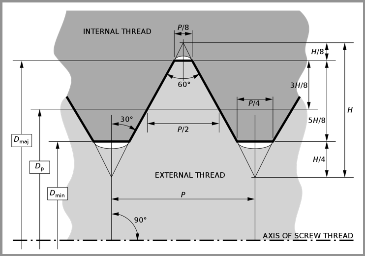
 Class of fit for a cutting tap refers to the specific tolerance or fit that is desired between the threads of the tap and the threads of the hole it is being used to create. In other words, it defines how tightly or loosely the threads should mesh together. The class of fit is typically expressed using a combination of letters and numbers. The most commonly used standards for class of fit are the Unified Thread Standard (UTS) and the ISO metric thread standard. In the UTS, the class of fit is denoted by a combination of a letter and a number, such as 2B, 3A, etc. In the ISO metric thread standard, it is represented by a combination of a letter and a number, such as 6g, 4h, etc. For cutting taps, the class of fit is usually specified based on the intended application and the level of precision required. The class of fit can affect factors like the ease of assembly, the strength of the threaded connection, and the ability to engage the threads smoothly during tapping. A classification system exists for ease of manufacture and interchangeability of fabricated threaded items. Most, but certainly not all, threaded items are made to a UTS classification standard. This system is analogous to the fits used with assembled parts.
The letter suffix "A" or "B" denotes whether the threads are external or internal, respectively. Classes 1A, 2A, 3A apply to external threads; Classes 1B, 2B, 3B apply to internal threads Here are some common classes of fit for cutting taps:
The standard designation for a UTS thread is a number indicating the nominal (major) diameter of the thread, followed by the pitch measured in threads per inch. For diameters smaller than 1⁄4 inch, the diameter is indicated by an integer number defined in the standard; for all other diameters, the inch figure is given.
This number pair is optionally followed by the letters UNC, UNF or UNEF (Unified) if the diameter-pitch combination is from the coarse, fine, or extra fineseries, and may also be followed by a tolerance class. Example: #6-32 UNC 2B (major diameter: 0.1380 inch, pitch: 32 tpi) 
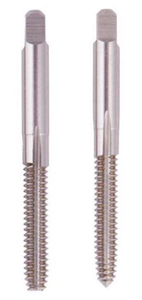
Technical article courtesy of Regal Cutting Tools Most craftspeople will agree that whenever an internal thread can be made with a roll form tap, this is the tool that should be used for the job. Roll taps, also known as form taps, hold distinct advantages over cut taps. Roll tap advantages are inherent in the way they create the threads. As the names suggest, these taps form the threads by rolling and deforming the material inside the hole. They push the metal out of the way to create the thread roots and base. Cut taps, also true to their name, carve metal away from inside the hole, ejecting chips as they go. Reasons to Use Roll Form TapsRoll taps are a great option when considering workmanship and price point. First, roll taps are chipless. Because they do not remove material from the hole, form taps generate no chips that must be removed. This carries several advantages:
When Not to Use Roll TapsWhile an excellent choice for most applications, there are a few situations that do not lend themselves to roll tapping including:
Types of Roll TapsRoll taps are engineered and manufactured in two main styles to match the type of hole and fastener to be used. Bottoming roll taps feature little to no taper on their end threads. This allows full thread production to the very bottom of the hole.
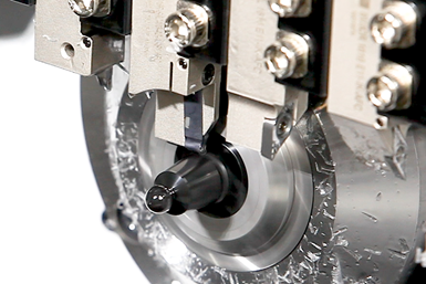
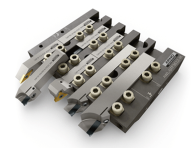
The bottom 3 to 5 threads on a plug tap are tapered to allow the tap to gradually begin deforming the hole material, creating less stress on the tool and giving the full threading edges a base from which to work. Regal Cutting Tools has built a reputation for high quality taps and other metalworking tools and an uncompromising commitment to customer service. Regal manufactures a full line of roll taps to suit any application. Regal can even engineer custom taps quickly and affordably. To learn more about Regal’s taps and learn which products are best suited for your workflow, contact our team today. Appears in Print at Production Machining as: 'A Swift Tool Change for Swiss-Type Machines' This coolant-through tooling system replacement for the gang plate on a Swiss-type machine can save hours of spindle downtime per day as well as increase tool life and enhance chip control. While servicing the tools on a traditional platen on a sliding headstock lathe, it can take 10 minutes or more to index one insert. While indexing the tools, coolant spigots can get knocked loose by an operator and can cost a machine shop tool life and time. Once the inserts are indexed, it can take several starts and stops of the spindle for the operator to see if the coolant stream is being directed to where it needs to be.
Arno’s Fast Change (AFC) tooling system consists of a gang plate that holds split-shank, coolant-through turning tools, parting tools and grooving tools. Designed like a manifold, the coolant is rerouted through the gang plate to the tools. The UN-style slot in the fixed stop picks up the coolant and runs it through the pipette to the front end where the coolant goes directly to the cutting edge. The AFC system can supply coolant to one port that supports all the tooling positions, or it can supply two ports and divide the tooling positions with the needle valve. The tooling system only needs to be plumbed once and, according to the company, after that, a high-pressure coolant line should not need to be touched again. With proper setup, the high-pressure lines are moved behind the machine guards, creating a clean machining environment. This enables operators to complete safer routine maintenance. Also, the AFC’s low-profile clamps do not collect as many chips compared with a typical clamping system. When replacing a split-shank tool, the operator simply loosens two clamps to remove the cutting head and then replaces it with a new one, the company says. Simple, Quick FunctionalityA Time and Money SaverUsing the AFC system, Arno reports that it takes 17 seconds to change a tool, a vast improvement to the typical 7 to 10 minutes it can take using a traditional gang plate. The conventional method might take five minutes to change a tool, a minute to touch the tool off and another minute to adjust the spigot, for instance.
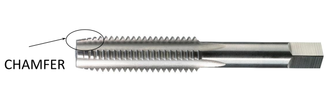
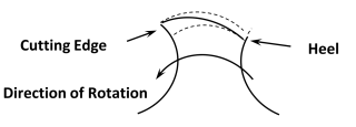
In comparison, when an operator is working with the AFC system, retouch is not necessary because the tool will repeat within plus or minus a thousandth of the previous tool positions. There is also no need to factor in time for readjusting coolant lines because the new system is a true, coolant-through system. It is also not necessary to factor in the clearing away of chips because those surfaces have mostly been eliminated with the smooth AFC design, according to Stroup. Therefore, the 17-second tool change time is the only time to factor in. But, for a real-world example, he increases the time to one minute to consider a distracted operator that might use extra seconds
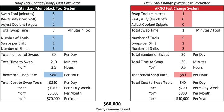
 Although there are still 30 idle times per day, there are now only 30 minutes of downtime per day instead of 210 minutes using the traditional gang plate. “That only costs $10,000 per year, which means you’ve just made $60,000 a year on that one spindle by adopting the AFC system,” Stroup says. Almost a year ago, Allen Benjamin, which has been a part of North American Tool, was purchased by GWS Tool Group. GWS Tool Group is a US-based, vertically integrated manufacturer of highly engineered custom, standard, and modified standard cutting tools, primarily servicing the aerospace and defense, power generation, automotive and medical sectors. GWS Tool Group has acquired multiple businesses in the course of its growth which now serves as the respective manufacturing divisions for the Company.
Just because there is a new owner, doesn't mean that the quality of an Allen Benjamin Tap has changed! If you’re in the market for high tensile strength carbide taps and metric taps, we can assure you that you’re in the right place. Not only is Allen Benjamin a leading supplier of the industry’s most durable, longest lasting carbide taps, we offer our customers the convenience of ordering online. In this day and age, we believe that quick access and top-notch customer services are critical. In today’s post, we’re going to look at why it is beneficial to order your carbide taps from Allen Benjamin. Quality Allen Benjamin carbide taps are highly efficient when tapping abrasive metals such as aluminum, non-ferrous metals, and exotic materials. With a much higher tensile strength than standard taps, their high-quality carbide taps can withstand the rigorous demands of your application. Selection Allen Benjamin offers a staggering range of carbide taps, metric taps, HSSE taps, tapping fluid, extensions, and more. If it’s taps that you are looking for, you can be confident that they’ve got them and have them ready for delivery. Service Allen Benjamin guarantees that all of their products will be the absolute best quality, within standard tolerances and dimensions, and consistent with application specifications. If their goods don’t meet your needs, you can contact us for a return authorization. At Allen Benjamin, they take pride in offering the industry’s best taps. But, more importantly, they aim to provide our customers with access to a simpler, faster way to order their operation’s critical parts, supplies, and components. If you’ve been searching for a supplier that will meet your needs and rise to meet your challenges contact us today! Have you ever had a tapping job that was so troublesome that it caused heartburn or acid indigestion due to broken taps, bad finish, short tap life, over or undersized threads, etc.? One way of avoiding or alleviating such a condition is accomplished with the use of a tap feature called “relief”. The definition of “relief” according to Marian Webster, is removal or lightening of something oppressive, painful, or distressing. For a tap, “relief” is the reducing of surface contact between the tap/tap feature and the part being tapped. Surface contact generates unwanted heat causing the issues mentioned above. Depending on the tap feature, relief is applied in a direction that is, radially, around the tap, or axially, along the axis of the tap. All taps require a minimum number of features to have relief for it to cut, other reliefs are applied when the tapping application requires it. There are always tradeoffs when designing a tap, if a relief is applied or it’s amount is greater than necessary, it can cause the tap to run free or loose to a point it will cause heartburn or acid indigestion by producing issues mentioned above. Relieved features that are always necessary on a tap are: Chamfer, the tapered threads at the front of the tap. The crests or major diameter of the chamfered threads are radially relieved from the cutting edge to the heel of the land. Without this relief it would be like cutting a tomato with the non-sharp side of a knife, you can imagine the results of that. When looking at a taps chamfer, relief results in the crest width being wider at the cutting edge and narrowing towards the heel; 
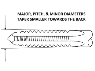
Back Taper, a slight gradual reduction of the taps thread form including it’s major, pitch and minor diameters. It starts at the chamfered end of the tap and continues axially for the length of thread towards the shank end.
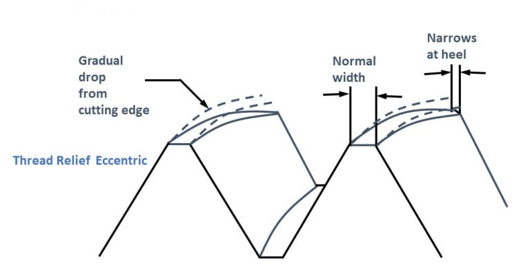
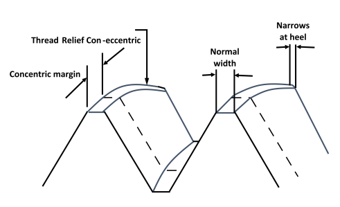
Additional features that can be relieved Thread Relief, a radial reduction of the taps major and pitch diameters from the cutting edge to the heel. Relieving of the pitch diameter results in the minor diameter being relieved as well due to the manufacturing process whereas the major diameter is relieved separately. The application of the major or pitch diameter relief is normally applied separately but both can be done in combination. Relief of pitch diameter is the most common followed by the major diameter. Thread relief is applied when Back Taper alone is not enough to prevent surface contact when tapping materials that close in and squeezes the tap like stainless steel. The rate of reduction from the cutting edge to the heel is based on the material being tapped and, in some cases, the tapping application. There are two common types of Thread Reliefs:
The reliefs we have discussed so far are applied during the tap manufacturing and other than the chamfer relief cannot be added or changed. If you are in a bind and must ship parts but can’t wait for us to design, manufacture and ship the appropriate tap, there are additional types of relief that can be applied that may work in a pinch. Sometimes referred to as a poor man’s relief, something you may be capable of doing in your shop without too much trouble to get you through a quick job, or until properly designed tools arrive. 
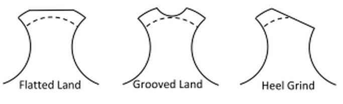
The application of relief types and amounts are dependent on many factors such as material properties being tapped, style and size of tap, how the tap is being used (hand, machine, etc.) and application requirements, etc. By providing us with as much information about your tapping application, it will enable our engineers to design a tap with the proper relief. This will help alleviate troublesome heartburn or acid indigestion. Edit January 2024: Changed banner image
The Dümmel Minimill-System with three or six cutting edges is the next big thing for ultra groove milling and threading machining from 0mm to a 32mm bore diameter. The indexable carbide heads are screwed on with three ribs coupling. This guarantees the best possible rotation and repeatable accuracy. A large selection of standard inserts as well as toolholders from steel and carbide are available from stock. With six cutting tools available, there's sure to be one that you can use to generate higher feed rates, longer tool life with higher stock removal rates. The six cutting edged Minimill-system is also available with an anti-vibration carbide toolholder or a steel tool holder. North American Tool realizes how confusing the painstaking math is to get preplate part limits and a Tap “H” limit, but don’t worry, all you have to do is contact us with your thread information, and we will do the work. Call us at 800-USA-TAPS. If you want to know how it's done, we’ve included the formulas for the engineer in all of us. If you want to know how it’s done, we’ve included the formulas for the engineer in all of us. When encountering an internal threaded hole requiring it to be plated, it normally needs to be produced oversize to accommodate the plating. There are two methods for determining the correct Tap “H” limit, the “Detailed Method” and the “Simplified Method”. The “Detailed Method” requires you to do more math, but it will also determine the before plate product limits (GO & NOGO) The “Simplified Method” requires less math but will not provide you with the before plate product limits (GO & NOGO) When the plating is applied to the properly oversized threaded hole, the required thread class (2B, 3B) or special PD (pitch diameter) will be met. The effect of plating on a 60° screw thread is a change in PD of 4 times the plating thickness (2 times on each side). That is because the plating itself is parallel to the thread flanks, and the PD is measured perpendicular to the thread axis. As an example, a .0002 plating thickness X 4 results in a PD increase of .0008 (The ratio of 4:1 is for 60° threads only, the ratio for other thread forms such as ACME, 29° is different.) Detailed MethodBefore determining the tap size (H limit), it is necessary to determine the oversize part thread limits first. Once this is achieved, the tap limit is normally position at 40% of the before plate limits. Unfortunately, life is not always easy. The required plating thickness on the print, purchase order, etc. will be expressed in one of two ways, a “Maximum and Minimum Thickness” or a “One Value Thickness” requiring two different ways to calculate the oversize part thread limits. Maximum and Minimum Plating Thickness 1. The Minimum part PD (pitch diameter) is larger by 4 X the Maximum plating thickness 2. The Maximum part PD (pitch diameter) is larger by 4 x the Minimum plating thickness 3. The Tap “H” = a PD that is located at 40% of the before plate limits – minimum after plate limit \ .0005 (“H” limit increment). Selecting the closes “H” limit Example: 1/4-20 UNC-2B, plating thickness, .0002 to .0003 (1/4-20 UNC-2B after plate PD = .2175 – .2224) 1. GO Minimum before coating part PD (pitch diameter) =.2175 (after plate GO or minimum PD) + .0012 (4 X .0003 max plating thickness) = .2187 2. NOGO Maximum before coating part PD (pitch diameter) = .2224 (after plate NOGO or maximum PD) + .0008 (4 X .0002 min plating thickness) = .2232 3. Tap ‘H” Limit .2232 (Maximum before coating part PD) – .2187 (Minimum before coating part PD) = .0045 .0045 X 40% = .0018 .0018 + 2187 (Minimum before coating part PD) = .2205 .2205 (before plate Tap PD) – .2175 (after plate or minimum PD) = .003 0.003 / .0005 (“H” limit increment) = H6 One Value Plating Thickness When a “One Value Plating Thickness” is shown, we establish a maximum and minimum plating thickness values to compute the maximum and minimum before platting thread limits. This is done by assuming that the tolerance on the plating is 50% larger than the “One Value Plating Thickness.” The maximum plating thickness is 6 X, the “One Value Plating Thickness,” and the minimum plating thickness is the same as the “One Value Plating Thickness.” 1. The Minimum part PD (pitch diameter) is larger by 6 X the “One Value Plating Thickness” 2. The Maximum part PD (pitch diameter) is larger by 4 x the “One Value Plating Thickness” 3. The Tap “H” = a PD that is located at 40% of the before plate limits – minimum after plate limit \ .0005 (“H” limit increment). Selecting the closes “H” limit Example: 1/4-20 UNC-2B, plating thickness, .0003 (1/4-20 UNC-2B after plate PD = .2175 – .2224) 1. GO Minimum before coating part PD (pitch diameter) =.2175 (after plate GO or minimum PD) + .0018 (6 X .0003 “One Value Plating Thickness”) = .2193 2. NOGO Maximum before coating part PD (pitch diameter) = .2224 (after plate NOGO or maximum PD) + .0012 (4 X .0003 “One Value Plating Thickness”) = .2236 3. Tap ‘H” Limit .2236 (Maximum before coating part PD) – .2193 (Minimum before coating part PD) = .0043 .0043 X 40% = .00172 .00172 + .2193 (Minimum before coating part PD) = .2210 .2210 (before plate Tap PD) – .2175 (after plate or minimum PD) = .0035 0.0035 / .0005 (“H” limit increment) = H7 Simplified MethodThis method requires knowing what tap “H” limit that is recommended for the thread class of fit (2B 3B etc.) after plating.
Example: The recommended “H” limit for a 1/4 – 20 UNC 2B would be GH5 and for a 3B it would be GH3. Maximum and Minimum Plating Thickness When the plating thickness requirement is given with a maximum and minimum limit you would simply, Example: 1/4-20 UNC-2B, plating thickness, .0002 to .0003 (1/4-20 UNC-2B after plate recommended “H” limit GH5) One Value Plating Thickness When the plating thickness requirement is given with a one value plating thickness limit you would simply, Multiply the plating thickness by 4 (the 60° size change ratio) to determine the PD (pitch diameter) size change in inches. Then divide the PD size change in inches by .0005 (“H” limit increment). The result would be the increase in “H” limit and added to the recommended “H” limit for the required after plate thread class. Example: 1/4-20 UNC-2B, plating thickness, .0003 (1/4-20 UNC-2B after plate recommended “H” limit GH5) .0003 X 4 = .0012 (PD size change in inches) .0012 / .0005 = 2.4 (PD size change in “H” limits) rounder to the closest “H” limit = 2 Recommended “H” limit of GH5 (recommended “H” limit for Class 2B) + 2 = GH7 (pre-plate “H” limit) Arno Werkzeuge USA has reintroduced the H.B. Rouse brand of American-made carbide cutting tools and inserts. ![]() 
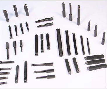
Arno Werkzeuge USA has reintroduced the H.B. Rouse brand of carbide cutting tools and inserts. Formerly sold and marketed under the Arno-Rouse name, the company has reintroduced Rouse as a standalone product offering a broad range of carbide boring bars, tools and inserts for manual turning operations. The carbide insert turning tools have triple-sided inserts for quick change turning operations. Triple-tip boring bars offer an improved triangular insert located within a precision-machined pocket to eliminate shifting under heavy cuts; the insert requires the simple removal of one screw for indexing. Boring bars feature carbide inserts that provide three cutting edges instead of only one (as is common with brazed-tip tooling). |
AuthorWe've compiled the latest news and technical information about our principals and our market that we hope you find informative! Archives
January 2025
Categories
All
|