|
written, compiled and edited by Bernard Martin Class of fit for a cutting tap refers to the specific tolerance or fit that is desired between the threads of the tap and the threads of the hole it is being used to create. In other words, it defines how tightly or loosely the threads should mesh together. The class of fit is typically expressed using a combination of letters and numbers. The most commonly used standards for class of fit are the Unified Thread Standard (UTS) and the ISO metric thread standard. In the UTS, the class of fit is denoted by a combination of a letter and a number, such as 2B, 3A, etc. In the ISO metric thread standard, it is represented by a combination of a letter and a number, such as 6g, 4h, etc. For cutting taps, the class of fit is usually specified based on the intended application and the level of precision required. The class of fit can affect factors like the ease of assembly, the strength of the threaded connection, and the ability to engage the threads smoothly during tapping. A classification system exists for ease of manufacture and interchangeability of fabricated threaded items. Most, but certainly not all, threaded items are made to a UTS classification standard. This system is analogous to the fits used with assembled parts.
The letter suffix "A" or "B" denotes whether the threads are external or internal, respectively. Classes 1A, 2A, 3A apply to external threads; Classes 1B, 2B, 3B apply to internal threads Here are some common classes of fit for cutting taps:
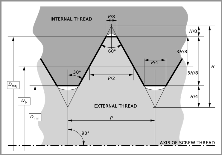
The standard designation for a UTS thread is a number indicating the nominal (major) diameter of the thread, followed by the pitch measured in threads per inch. For diameters smaller than 1⁄4 inch, the diameter is indicated by an integer number defined in the standard; for all other diameters, the inch figure is given.
This number pair is optionally followed by the letters UNC, UNF or UNEF (Unified) if the diameter-pitch combination is from the coarse, fine, or extra fineseries, and may also be followed by a tolerance class. Example: #6-32 UNC 2B (major diameter: 0.1380 inch, pitch: 32 tpi)
0 Comments
Browne & Co has been appointed as Regaional Managers for Regal Cutting Tools. They will be responsibilve for distributor and technical support for the Kentucky, Ohio, and Western Pennsylvania market areas. Regal Cutting Tools has been manufacturing world-class cutting tools since 1955 Regal offers a high performance SuperTuf series of taps for the demanding difficult to machine materials. Regal also manufactures special taps from blanks with as little as 24 hour notice.
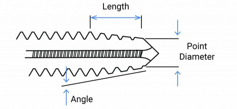
According to Dave Browne, President of Browne & Co, "Regal Cutting Tools. is a well established and trusted brand within the metalcutting industry. Their full line of taps as well as their tap specials capabilities really compliment our product mix and fills an area we have pretty deep experience in but didn't have a product to recommend. We're really looking forward to working with our customers and running these tools!" How can you optimize a tap's chamfer based on your application? Although North American Tool/ GWS stocks many common special taps with standard chamfer lengths, they can design and manufacture a special tap for your application. Optimizing the chamfer results in, longer tap life, reduced tapping torque, better finish, and make the difference between success and failure. As most of you know, the chamfer is the tapered section on the front of the tap. It includes the length, angle, radial relief, and point diameter. As the tap rotates and advances forward, each succeeding chamfered tooth enters the drilled hole and takes deeper and deeper cuts until the first full thread on the tap completes producing a full thread in the part. The balance of the tap’s threads within the length beyond the chamfer, do not do any cutting and just goes for the ride.
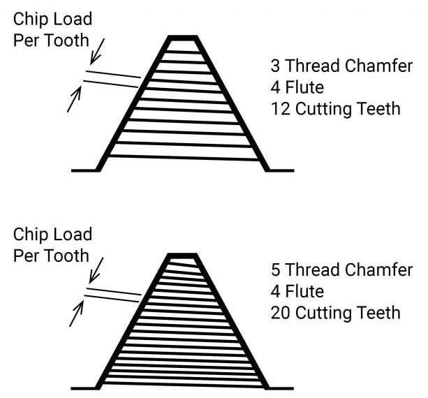
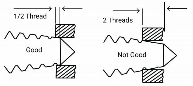
Increasing the total number of chamfered teeth cutting, can increase tap life exponentially. The example above shows that a standard plug chamfer (3 to 5 threads) length, so on a 4 fluted tap, it will range between 12 to 20 cutting teeth. Because North American Tool/ GWS understands more is better, they make it a point to manufacture our taps with a chamfer length closer to maximum length, in this case, 5 threads. This is also true for the other standard chamfer lengths Bottom, Semi Bottom, and Taper. Although more is better, you may be limited to the length of chamfer due to the job requirements. We should also note that the incomplete threads created and left in the part by the chamfer are not too full thread height and will cause assembly interference, therefore they are not considered part of the required thread length. As for manufactured specials, knowing your application requirements is necessary for us to design a tap that optimizes performance. For chamfer design, North American Tool/ GWS would need to know, tap drill size, tap drill depth, and full thread length requirement. Knowing the tap drill size allows us to grind a chamfer with a point diameter that permits the tap to start cutting within the first half thread of entry. Because there are many factors that go into determining a tap drill size, there can be a relatively wide range of diameters. If the chamfer point diameter is smaller than the tap drill diameter, then the tap may not start cutting until the second chamfer tooth or beyond. Using the same 4 flute, plug tap from the example above, in an application with a tap drill size larger than the chamfer point diameter, such that the tap does not start cutting till the 2nd chamfer tooth, will have a reduction in cutting teeth by 6 (1.5 threads X 4 flutes), or 30%. If the application is such that only a bottom chamfer (1 to 2 threads) can be used, and it is ground to the maximum length of 2 threads it will result in a reduction of cutting teeth from 8 (2 threads X 4 flutes) to 6 (1.5 threads X 4 flutes) or 75%. Knowing the tap drill depth and full thread length requirement also allows us to design the maximum length chamfer for your application. This may take into consideration the overspin of the machine spindle, or room at the bottom of a blind hole so the tap does not run into any chips that may have made their way to the bottom. Although the information presented may be confusing, hopefully we have explained the importance of the chamfer, and the many considerations that go into its proper design.
So, if you are ready to increase tap life, reduced tapping torque, improve the finish, and make the difference between success and failure, give us a call with your application requirements.
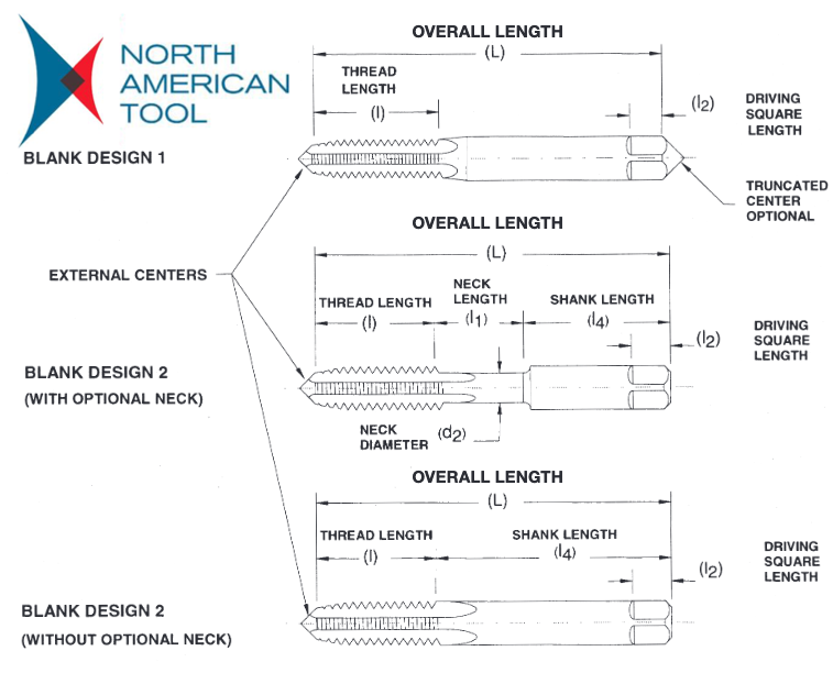
Choose from six rings to maximize tool life and improve thread quality. Here’s the key to selection: These tools are stocked standards. Fractional sizes are available from #0-80 up though 1”-8 and Metric sizes from M2.5 x 0.45 through M20 x 2.5. To compete for the gold with your customers, choose High Performance with Allen Benjamin Color-Ring Taps. edited by Bernard Martin Getting a good understanding of the definitions of the parts of a tap will help you to better understand the functions of tap designs. Special thanks to North American Tool for letting us share their short and simple explanations! ALLOWANCE Minimum clearance between two mating parts; the prescribed variations from the basic size. ANGLE OF THREAD The angle included between the sides of the thread measured in an axial plane. AXIS The imaginary straight line that forms the longitudinal centerline of the tool or threaded part. BACK TAPER A gradual decrease in the diameter of the thread form on a tap from the chamfered end of the land towards the back which creates a slight radial relief in the threads. BASE OF THREAD The bottom section of the thread; the greatest section between the two adjacent roots. BASIC SIZE The theoretical or nominal standard size from which all variations are derived by application of allowances and tolerances. CHAMFER The tapering of the threads at the front end of each land of a tap by cutting away and relieving the crest of the first few teeth to distribute the cutting action over several teeth; Taper taps are chamfered 7-10 threads; plug tapsare chamfered 3-5 threads; semi-bottoming (or modified bottoming) taps are chamfered 2-2.5 threads; bottom-ing taps are chamfered 1-2 threads; taper pipe taps are chamfered 2-3.5 threads. CHAMFER RELIEF The gradual decrease in land height from cutting edge to heel on the chamfered portion, to provide clearance for the cutting action as the tap advances. CREST The top surface joining the two sides or flanks of the thread; the crest of an external thread is at its major diameter, while the crest of an internal thread is at its minor diameter. CUTTING FACE The leading side of the land in the direction of cutting rotation on which the chip forms. FLUTE The longitudinal channels formed in a tap to create cutting edges on the thread profile, and to provide chip spaces and cutting fluid passages. HEEL The edge of the land opposite the cutting edge. HEIGHT OF THREAD The distance, measured radially, between the crest and the base of a thread. HELIX ANGLE The angle made by the advance of the thread as it wraps around an imaginary cylinder. HOOK The undercut on the face of the teeth. HOOK ANGLE The inclination of a concave cutting face, usually specified either as Chordal Hook or Tangential Hook.
INTERRUPTED THREAD TAP A tap having an odd number of lands with alternate teeth along the thread helix removed. In some cases alternate teeth are removed only for a portion of the thread length. LAND The part of the tap body which remains after the flutes are cut, and on which the threads are finally ground. The threaded section between the flutes of a tap. LEAD The axial distance a tap will advance along its axis in one revolution. On a single start, the lead and the pitch are identical; on a double start, the lead is twice the pitch. MAJOR DIAMETER Commonly known as the “outside diameter.” It is the largest diameter of the thread. MINOR DIAMETER Commonly known as the “root diameter.” It is the small-est diameter of the thread. PERCENT OF THREAD One-half the difference between the basic major diameter and the actual minor diameter of an internal thread, divided by the basic thread height, expressed as a percentage. PITCH The distance from any point on a screw thread to a cor-responding point on the next thread, measured parallel to the axis and on the same side of the axis. The pitch equals one divided by the number of threads per inch. PITCH DIAMETER On a straight thread, the pitch diameter is the diameter of the imaginary co-axial cylinder...the surface of which would pass through the thread profiles at such points as to make the width of the groove equal to one-half of the basic pitch. On a perfect thread this occurs at the point where the widths of the thread and groove are equal. On a taper thread, the pitch diameter at a given position on the thread axis is the diameter of the pitch cone at that position. RAKE
The angular relationship of the straight cutting face of a tooth with respect to a radial line through the crest of the tooth at the cutting edge.
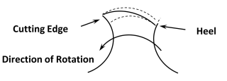
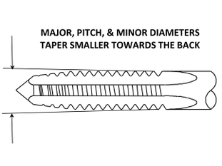
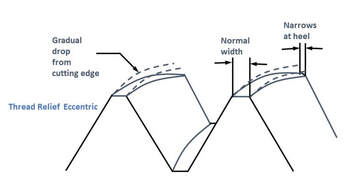
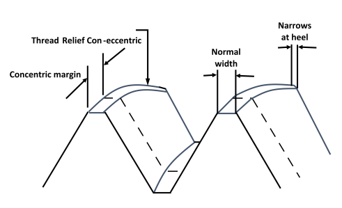
RELIEF (or Thread Relief) The removal of metal from behind the cutting edge to provide clearance and reduce friction between the part being threaded and the threaded land. ROOT The bottom surface joining the sides of two adjacent threads, and is identical with or immediately adjacent to the cylinder or cone from which the thread projects. SPIRAL FLUTE A flute with uniform axial lead in a spiral path around the axis of a tap. SPIRAL POINT The angular fluting in the cutting face of the land at the chamfered end; formed at an angle with respect to the tap axis of opposite hand to that of rotation. Its length is usually greater than the chamfer length and its angle with respect to the tap axis is usually made great enough to direct the chips ahead of the taps cutting action. STRAIGHT FLUTE A flute that forms a cutting edge lying in an axial plane. TOLERANCE In producing a tap to given specifications, tolerance is: (a.) the total permissible variation of a size; (b.) the difference between the limits of size. Have you ever had a tapping job that was so troublesome that it caused heartburn or acid indigestion due to broken taps, bad finish, short tap life, over or undersized threads, etc.? One way of avoiding or alleviating such a condition is accomplished with the use of a tap feature called “relief”. The definition of “relief” according to Marian Webster, is removal or lightening of something oppressive, painful, or distressing. For a tap, “relief” is the reducing of surface contact between the tap/tap feature and the part being tapped. Surface contact generates unwanted heat causing the issues mentioned above. Depending on the tap feature, relief is applied in a direction that is, radially, around the tap, or axially, along the axis of the tap. All taps require a minimum number of features to have relief for it to cut, other reliefs are applied when the tapping application requires it. There are always tradeoffs when designing a tap, if a relief is applied or it’s amount is greater than necessary, it can cause the tap to run free or loose to a point it will cause heartburn or acid indigestion by producing issues mentioned above. Relieved features that are always necessary on a tap are: Chamfer, the tapered threads at the front of the tap. The crests or major diameter of the chamfered threads are radially relieved from the cutting edge to the heel of the land. Without this relief it would be like cutting a tomato with the non-sharp side of a knife, you can imagine the results of that. When looking at a taps chamfer, relief results in the crest width being wider at the cutting edge and narrowing towards the heel; Back Taper, a slight gradual reduction of the taps thread form including it’s major, pitch and minor diameters. It starts at the chamfered end of the tap and continues axially for the length of thread towards the shank end.
Additional features that can be relieved Thread Relief, a radial reduction of the taps major and pitch diameters from the cutting edge to the heel. Relieving of the pitch diameter results in the minor diameter being relieved as well due to the manufacturing process whereas the major diameter is relieved separately. The application of the major or pitch diameter relief is normally applied separately but both can be done in combination. Relief of pitch diameter is the most common followed by the major diameter. Thread relief is applied when Back Taper alone is not enough to prevent surface contact when tapping materials that close in and squeezes the tap like stainless steel. The rate of reduction from the cutting edge to the heel is based on the material being tapped and, in some cases, the tapping application. There are two common types of Thread Reliefs:
The reliefs we have discussed so far are applied during the tap manufacturing and other than the chamfer relief cannot be added or changed. If you are in a bind and must ship parts but can’t wait for us to design, manufacture and ship the appropriate tap, there are additional types of relief that can be applied that may work in a pinch. Sometimes referred to as a poor man’s relief, something you may be capable of doing in your shop without too much trouble to get you through a quick job, or until properly designed tools arrive. The application of relief types and amounts are dependent on many factors such as material properties being tapped, style and size of tap, how the tap is being used (hand, machine, etc.) and application requirements, etc. By providing us with as much information about your tapping application, it will enable our engineers to design a tap with the proper relief. This will help alleviate troublesome heartburn or acid indigestion. Edit January 2024: Changed banner image
First things first, what is the root of a tap?
The root of a tap is the surface at the bottom of the thread-form that connects adjacent thread flanks and is expressed as a width or as a diameter. The term root diameter is also called minor diameter, it’s one of those things, you say rain and I say precipitation, meaning the same thing... Many people will first be exposed to threading tool features in the form of a quote request, or order, from a customer. Example: Please quote 6 pieces of a 1"-20 NEF HSS 2B LH GH-3 6-FL PL tap. Dissected, the customer has defined this tap as one with a "major" or "outside diameter" measuring 1 inch, with 20 threads per inch.
Additional information provided in a description may also include the need for a surface treatment, or coating, or a specific geometry for cutting edge or flutes. Extended length to suit the application may also be noted. If additional information provided does not fit the common ones described above, please share it with Browne Sales. The experts here can interpret the information to assign it's importance to the completion of the finished tool as quoted, or ordered. *Be aware that all of the details of the description provided may not be marked on the finished tap, usually because of space constraints on the shank of the tool. Important pieces of information including; Material being tapped, depth of thread being produced, and type of hole (through or blind) being tapped, may also be included in the description. If these details are not included, the questions should be asked. This information will go a long way towards providing the you with a tool applicable to the job at hand. |
AuthorWe've compiled the latest news and technical information about our principals and our market that we hope you find informative! Archives
June 2024
Categories
All
|
|
Browne & Co., Inc.
9605 Tanager Drive Chardon, Ohio 44024 |
© 2024 Browne & Co., Inc. All Rights Reserved
web design by Rapid Production Marketing |










 RSS Feed