|
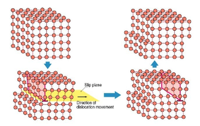
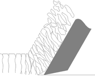
Contrary to popular terminology, metal is not “cut” as much as it is a “forced separation from itself.” To understand this, think of how molecules bond together. Molecules resemble our solar system with the nucleus represented by our Sun (or a carbon atom in the image) and the electrons represent by the various planets. When one molecule “bonds” with another it is as if two solar systems’ planets became intertwined into each others orbits with both solar systems sharing certain planets and making the whole larger than the sum if it’s parts. When we use a cutting tool we are inducing these bonds to break apart. The “machinability” of a particular metal partially defines how easily the material separates from itself. The basic mechanics of forming a chip are the same regardless of the base material. As the cutting tool engages the workpiece, the material directly ahead of the tool is sheared and deformed under tremendous pressure. The deformed material then seeks to relieve its stressed condition by fracturing and flowing into the space above the tool in the form of a chip. The important difference is how the chip typically forms in various materials. Regardless of the tool being used or the metal being cut, the chip forming process occurs by a mechanism called plastic deformation. This deformation can be visualized as shearing. That is when a metal is subjected to a load exceeding its elastic limit. The crystals of the metal elongate through an action of slipping or shearing, which takes place within the crystals and between adjacent crystals. Type 1: Discontinuous ChipCast Iron, Hard Brass and other materials that produce a Powdery chip. “Discontinuous Chip - Discontinuous or segmented chips are produced when brittle metal such as cast iron and hard bronze are cut or when some ductile metals are cut under poor cutting conditions.
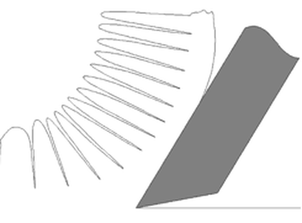
Type 2: Continuous ChipMedium to High carbon and alloy Steels – Long Chipping Materials “Continuous Chip - Continuous chips are a continuous ribbon produced when the flow of metal next to the tool face is not greatly restricted by a built-up edge or friction at the chip tool interface. The continuous ribbon chip is considered ideal for efficient cutting action because it results in better finishes. Unlike the Type 1 chip, fractures or ruptures do not occur here, because of the ductile nature of the metal.”
Type 3: Sheared ChipsLow carbon Steels, Stainless Steels, Nickel Alloys, Titanium, Copper, Aluminum and other soft, “gummy’ Materials. Sheared Chips or as some refer to it “Continuous Chip with a Built-up Edge (BUE). The metal ahead of the cutting tool is compressed and forms a chip which begins to flow along the chip-tool interface.
These metals readily deform in front of the cutting edge and have to be "sheared" by the tool. What the above paragraph doesn’t tell you is that these materials require tools with sharper cutting edges than those used for machining cast Iron or higher carbon content Steels. The chips tend to compress onto the face of the tool which can result in built-up edge.
The chips formed when cutting these metals are thicker than those produced by Medium Carbon or Alloy Steels at the same Feed Rates and Depths of Cut. These thicker chips are stronger and harder to break. Destiny Tool, through a combination of rake face geometry, carbide substrate and concentricity tolerance is able to enable the chip to more readily "separate from itself" which not only improves MRR, but also reduced heat into the end mill and thereby extends tool life as the feed rate increases. High strength metals such as Stainless Steel, Nickel Alloys and Titanium generate high heat and high cutting pressures in the area of the cutting edge. This results in reduced tool life compared to easier to machine materials.
0 Comments
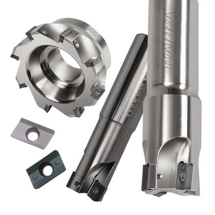
Choosing the right insert geometry and grade for an application can easily make or break a job. Making the right choice requires educating yourself on what types of cutting edge and carbide grades are best suited to the machining conditions present.
Grade SelectionDapra uses an easy-to-understand system that separates grades by toughness/hardness. The same coatings are available for each carbide substrate, so choosing the grade begins with the toughness of the substrate desired and ends with the coating of choice. For abusive applications, use of the toughest grade is recommended. These would be identified as the following: interrupted cuts; long tool lengths; poor chip evacuation; stainless steels; high-temperature alloys; poor workpiece or machine rigidity; coolant use or very heavy cut depths.
For stable, steel and ductile iron applications, Dapra recommends our medium toughness/hardness carbide. Examples of some good applications include: uninterrupted steel cuts; good workholding / machine rigidity; short tool / diameter ratios; lighter depths of cut; good chip evacuation; alloys; low and high carbon steels; ductile (long-chipping) irons; and dry machining.
For very stable, high-wear applications in cast iron and nonferrous materials, as well as hard milling of heat-treated materials, Dapra recommends the use of our hardest grades. Application examples include: gray cast irons; aluminum and copper alloys; plastics; light, smooth cuts in any material; and heat-treated steels (typically over 48 Rc).
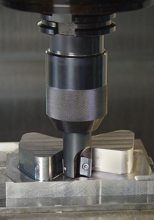
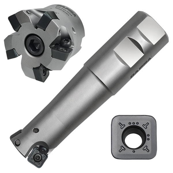
Geometry SelectionDapra offers three different cutting edges for the Square Shoulder milling line:
General RecommendationsMaterial Being Machined Use stronger, T-land cutting edges for steels and cast irons. Use sharper honed edges for stainless steels and high-temperature alloys. For aluminum and plastics, use sharp, un-honed cutting edges. Workholding / Machine Tool Rigidity Use the recommended grades and geometries for rigid setups and machines. In cases where rigidity is lacking (light-duty machine, poor workholding, etc.), use tougher grades and stronger geometries. The exception to this rule is when the use of the sharper geometry (XPET) actually stops or reduces the vibration created by the poor rigidity. These situations typically present a "trial and error” scenario.
Long Toolholder / Length to Diameter Ratio
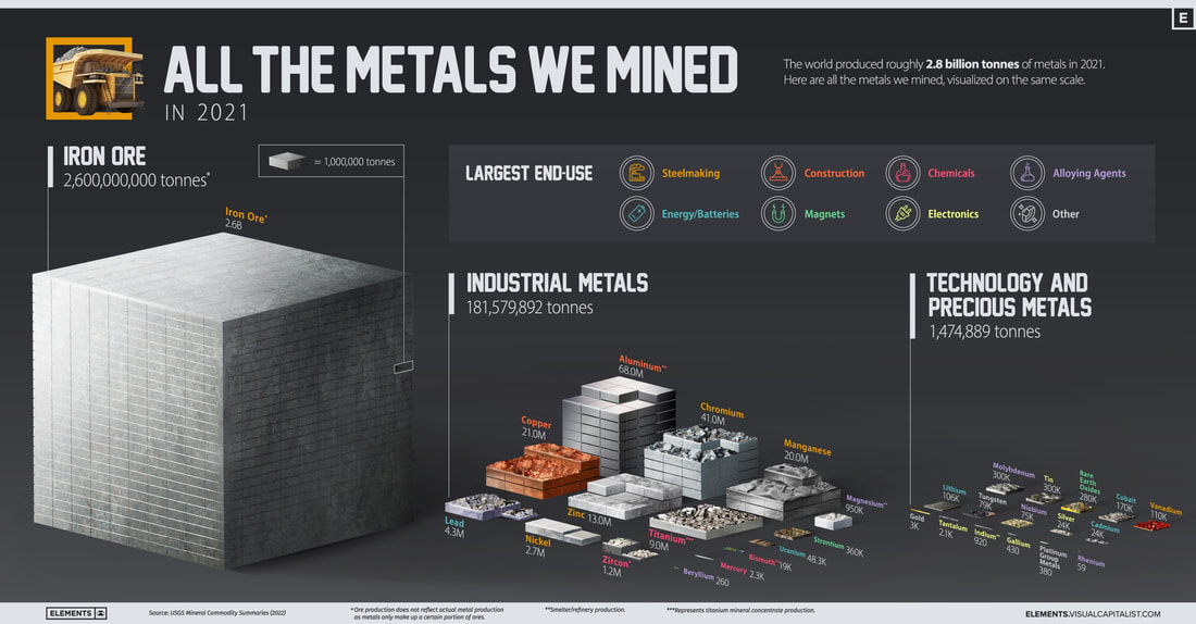
This situation closely resembles the previous rigidity issue. Long tool lengths (including longer tool holders) decrease tool rigidity, creating the potential for chatter and vibration. This can typically be combated with stronger cutting edges, but can also sometimes be corrected with a sharper, free cutting edge. Use the APET unless the results prohibit the use of such a strong edge. The XPET may reduce vibration enough to quiet the operation. Again, use of the toughest grades is typically recommended in long reach applications where chatter or vibration is present. Coolant vs. Dry Machining Most applications using Dapra cutting tools are best performed using dry air blast. Exceptions to this rule include: high-temperature alloys, aluminum and some exceptionally tough stainless steels. When dry machining, use the grades and geometries suggested previously. When using coolants, Dapra recommends using the tougher grades, but with sharper cutting edges (XPET). This allows the heat generated in the cutting zone to be minimized, delaying the effects of thermal shock. Machining Parameters For heavier cuts, tougher substrates should be used, due to the increased pressure and potential vibration created. In lighter cuts, the harder grades provide better performance (speed) and longer tool life. The minimum FPT (feed per tooth) for the APET geometry should be .006". This is to get the chip thickness past the T-land edge preparation, allowing the insert to cut, not rub. The minimum FPT for the XPET insert should be .003". Consequently, lighter cuts (FPT) should not be taken with the APET unless other conditions exist that necessitate the use of the stronger edge. The selection procedure described here will require your careful consideration of several application conditions and insert characteristics. This may take some time, but the cutting results will be well worth your effort. From: Visual Capitalist The world produced roughly 2.8 billion tons of metal in 2021. This chart represents the metals we mined, visualized on the same scale. This was originally posted on Elements. “If you can’t grow it, you have to mine it” is a famous saying that encapsulates the importance of minerals and metals in the modern world. From every building we enter to every device we use, virtually everything around us contains some amount of metal. The above infographic visualizes all 2.8 billion tonnes of metals mined in 2021 and highlights each metal’s largest end-use using data from the United States Geological Survey (USGS). This article is courtesy of Regal Cutting Tools. Different tool engineering, composition, and design affect the way they perform and which workpieces they will cut most effectively. Several factors determine which drill bits work best on various steels and alloys, copper, zinc, aluminum, tin, etc., owing to the properties of ferrous vs. nonferrous metals. Properties of Ferrous and Non-Ferrous MetalsFerrous Metals Ferrous metals, of course, are those that contain iron. These include stainless, carbon, and alloy steel, and cast and wrought iron. Ferrous metals generally possess more tensile strength than their non-iron-based counterparts. That makes them ideal for use in building materials, structural and ornamental designs, and heavy industrial products such as shipping containers, tools, and appliances. Tool manufacturers must consider hardness and strength when designing and engineering drills made for cutting ferrous metals. Non-ferrous Metals Non-ferrous metals - especially copper, lead, zinc, and tin also occupy important niches in the construction and manufacturing industries. Because they contain no iron, these metals are valued for their use in applications where they come into contact with moisture that would rust ferrous metals. They also are malleable, ductile, and easily manipulated into various shapes for components, housings, etc. They are non-magnetic, making them quite useful in electronic components. Hardness is the primary consideration when choosing a drill to cut metal. Drills incorporate various design elements in order to cope with these different challenges Points and AnglesDrill bit points can be altered to provide more precise hole-starting, centering, and quality, as well as conduciveness to varying feeds and speeds. The standard 118-degree point is used because it offers a “good enough” fit for most applications. Standard points can be used for most “softer” steels and non-ferrous metals. Standard 135-degree split-point drills can cut these materials, as well as harder steel alloys. In these harder materials, the split-point offers the advantage of working at lower feed pressure and centering of the hole with minimal walking. Learn more about how to find the right drill point angle for your application FlutesThe grooves cut into drill bits (called flutes) serve two purposes:
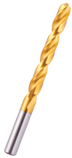
As we might expect, the harder the material being drilled, the harder the tool must be to get the job done. Carbon steels are too soft for cutting metal; only high-speed steel (HSS), carbide-tipped, and solid carbide bits should be used in cutting metal, no matter how soft. HSS is common because of its low cost and ability to drill softer carbon steels as well as zinc, copper, aluminum, and other non-ferrous metals. Alloying HSS with 5 to 8% cobalt adds “red” hardness which allows the tool to maintain the sharp cutting edge longer and allows for slightly faster speeds, making these drills suitable for working in heat-treated steel, cast iron, and even some titanium alloys. For exponential increases in speed and wear resistance, nothing beats using a carbide tool. It withstands extremely high temperatures, resists wear, and maintains rigidity better that HSS. It costs much more, but is the only long term, high volume option when the work piece is stainless steel or alloyed steel. Carbide-tipped HSS saves some costs and is a viable option for nonferrous metals such as copper, bronze, and other materials that are highly abrasive. Drills made of cobalt-alloy High Speed Steel (HSS-E) or even drill bits with a thin film coating are needed for stainless steel. These are more expensive than normal HSS drill bits, but they enable drilling in special steel without a high level of drill bit wear. Thin film coated drill bits are high-speed steel drill bits (HSS) that have any of a variety of coating blends typically with a titanium base. TiN (Titanium Nitride), TiALN (Titanium Aluminum Nitride) and TiCN (Titanium Carbonitride) are examples of thin film coaing typically used on drill bits. They are very hard, and corrosion-resistant and reduce the co-efficient of friction allowing for better lubrication of the tool. They last much longer than regular HSS drill bits, and they are good for cutting through any metal, including metal sheeting. Thin film coated drill bits have a surface that is harder than cobalt. However, because they are coated, they lose the coating protection at the cutting edge when they are re-sharpened and subsequent tool life will be reduced. Uncoated drill bits are made of cobalt or HSS steel, and they can be sharpened without any loss in performance or tool life.
ConstructionFerrous vs. Non-Ferrous MetalsUnderstanding the characteristics of ferrous and non-ferrous metals, and what twist drill is ideal for each material is key to high quality production and extending tool life. If you are still unsure of exactly which drill is right for your job, contact a Browne & Co. Sales Rep and we would be happy to assist you.
|
AuthorWe've compiled the latest news and technical information about our principals and our market that we hope you find informative! Archives
June 2024
Categories
All
|
|
Browne & Co., Inc.
9605 Tanager Drive Chardon, Ohio 44024 |
© 2024 Browne & Co., Inc. All Rights Reserved
web design by Rapid Production Marketing |

 RSS Feed