Highly abrasive materials like cast iron, polymers, glass filled polycarbonates, and some cast aluminum are called “hard” materials for a reason. They’re hard to machine, hard on tool life and hard on production cycle times. How do you overcome the difficulties of making parts out of challenging raw stock? By using a tool that’s even tougher. Consider a change from steel taps to carbide taps. When to Use Carbide Taps
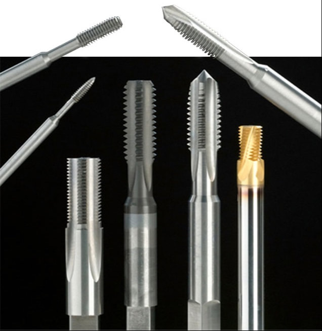
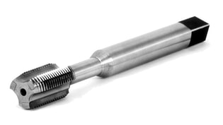
We offer carbide taps in UN and Metric sizes as well as straight and NPT/F Pipe and STI Standards. A wide range of styles and features are available, including straight flute, spiral flute, spiral point, and forming taps. For increased performance and life, we can customize tools with a full line of surface coatings such as TiN, TiCN, and TiALN. How to Use Carbide TapsMachining with carbide does come with some “do’s and don’t”. Hand tapping is generally not recommended. Rigid tapping and spot-on alignment are critical to avoid breakage. Not to worry, however. Modern CNC equipment is ideally suited for carbide applications. Here’s some additional tips. Coolant holes through the taps are an option for flushing chips out of the holes on the most difficult materials like some of the tougher stainless steels and space-age alloys. Carbide STI (Screw Thread Insert) tapping of these materials has become commonplace in the aeronautical and aerospace industries. The Why of Carbide TapsAlthough initially more expensive than HSS taps, significant savings can be realized, especially in long-run jobs. Higher cutting speeds, greater tool life, and reduced downtime from fewer tooling changes translate into reduced machining costs.
An alternative to costly larger sizes is our line of CarbISert® Taps. Solid carbide cutting surfaces are bonded onto a high-speed steel body to provide the best of both worlds; durability of carbide with the “forgiveness” of a steel body and shank. So, don’t let difficult materials give you a “hard” time. Contact us anytime and put our carbide taps to work for you. Watch for Part 2 of this series on carbide taps! Coming in August 2021: The Different Types of Carbide Taps and When to Use Them
1 Comment
Almost a year ago, Allen Benjamin, which has been a part of North American Tool, was purchased by GWS Tool Group. GWS Tool Group is a US-based, vertically integrated manufacturer of highly engineered custom, standard, and modified standard cutting tools, primarily servicing the aerospace and defense, power generation, automotive and medical sectors. GWS Tool Group has acquired multiple businesses in the course of its growth which now serves as the respective manufacturing divisions for the Company.
Just because there is a new owner, doesn't mean that the quality of an Allen Benjamin Tap has changed! If you’re in the market for high tensile strength carbide taps and metric taps, we can assure you that you’re in the right place. Not only is Allen Benjamin a leading supplier of the industry’s most durable, longest lasting carbide taps, we offer our customers the convenience of ordering online. In this day and age, we believe that quick access and top-notch customer services are critical. In today’s post, we’re going to look at why it is beneficial to order your carbide taps from Allen Benjamin. Quality Allen Benjamin carbide taps are highly efficient when tapping abrasive metals such as aluminum, non-ferrous metals, and exotic materials. With a much higher tensile strength than standard taps, their high-quality carbide taps can withstand the rigorous demands of your application. Selection Allen Benjamin offers a staggering range of carbide taps, metric taps, HSSE taps, tapping fluid, extensions, and more. If it’s taps that you are looking for, you can be confident that they’ve got them and have them ready for delivery. Service Allen Benjamin guarantees that all of their products will be the absolute best quality, within standard tolerances and dimensions, and consistent with application specifications. If their goods don’t meet your needs, you can contact us for a return authorization. At Allen Benjamin, they take pride in offering the industry’s best taps. But, more importantly, they aim to provide our customers with access to a simpler, faster way to order their operation’s critical parts, supplies, and components. If you’ve been searching for a supplier that will meet your needs and rise to meet your challenges contact us today! How can you optimize a tap's chamfer based on your application? Although North American Tool/ GWS stocks many common special taps with standard chamfer lengths, they can design and manufacture a special tap for your application. Optimizing the chamfer results in, longer tap life, reduced tapping torque, better finish, and make the difference between success and failure. As most of you know, the chamfer is the tapered section on the front of the tap. It includes the length, angle, radial relief, and point diameter. As the tap rotates and advances forward, each succeeding chamfered tooth enters the drilled hole and takes deeper and deeper cuts until the first full thread on the tap completes producing a full thread in the part. The balance of the tap’s threads within the length beyond the chamfer, do not do any cutting and just goes for the ride.
Increasing the total number of chamfered teeth cutting, can increase tap life exponentially. The example above shows that a standard plug chamfer (3 to 5 threads) length, so on a 4 fluted tap, it will range between 12 to 20 cutting teeth. Because North American Tool/ GWS understands more is better, they make it a point to manufacture our taps with a chamfer length closer to maximum length, in this case, 5 threads. This is also true for the other standard chamfer lengths Bottom, Semi Bottom, and Taper. Although more is better, you may be limited to the length of chamfer due to the job requirements. We should also note that the incomplete threads created and left in the part by the chamfer are not too full thread height and will cause assembly interference, therefore they are not considered part of the required thread length. As for manufactured specials, knowing your application requirements is necessary for us to design a tap that optimizes performance. For chamfer design, North American Tool/ GWS would need to know, tap drill size, tap drill depth, and full thread length requirement. Knowing the tap drill size allows us to grind a chamfer with a point diameter that permits the tap to start cutting within the first half thread of entry. Because there are many factors that go into determining a tap drill size, there can be a relatively wide range of diameters. If the chamfer point diameter is smaller than the tap drill diameter, then the tap may not start cutting until the second chamfer tooth or beyond. Using the same 4 flute, plug tap from the example above, in an application with a tap drill size larger than the chamfer point diameter, such that the tap does not start cutting till the 2nd chamfer tooth, will have a reduction in cutting teeth by 6 (1.5 threads X 4 flutes), or 30%. If the application is such that only a bottom chamfer (1 to 2 threads) can be used, and it is ground to the maximum length of 2 threads it will result in a reduction of cutting teeth from 8 (2 threads X 4 flutes) to 6 (1.5 threads X 4 flutes) or 75%. Knowing the tap drill depth and full thread length requirement also allows us to design the maximum length chamfer for your application. This may take into consideration the overspin of the machine spindle, or room at the bottom of a blind hole so the tap does not run into any chips that may have made their way to the bottom. Although the information presented may be confusing, hopefully we have explained the importance of the chamfer, and the many considerations that go into its proper design.
So, if you are ready to increase tap life, reduced tapping torque, improve the finish, and make the difference between success and failure, give us a call with your application requirements. If you deal with exotic alloys like Inconel, titanium, Hastelloy, etc., this article is written especially for you. Wise operators always select the correct tool for the job, avoiding the problems others face when they try to apply a general-purpose tool to a unique situation. In this article, we give you the information you need to select the proper tools for machining exotics. It will make your shop stand out from the competition since you will produce better results at a reduced cost. The Hard Stuff Exotic alloys are specifically designed for high-temperature applications (think aerospace), performance in corrosive environments (think underground), or to have the highest available strength to weight ratios (think earth-moving applications). The machinability of these materials is NOT the first consideration. As much as it would be nice from the machinist’s viewpoint to have an aluminum firewall in a helicopter, as the pilot or passenger you want a material that is strong and heat retardant.
The Answer
One day a new job order comes in and you are faced with threading these kinds of alloys. What’s an operator to do? Fortunately for you, North American Tool manufactures application-specific thread mills right here in the USA. These tools are made from solid carbide and have been specially designed with exotic materials in mind. The results are longer more consistent tool life and the elimination of scrap due to tap failures in your parts. Uniquely Crafted North American Tool thread mills for exotic alloys are designed with only three teeth. This places less stress on the tool than a conventional thread mill with six, eight, or ten teeth engaged in the workpiece at the same time. Carbide thread mills nickel-based alloys are also made with left-hand helix and left hand-cut, which permit an operator to run from the top of the hole to the bottom and climb mill the threads. This will create a right-hand thread on the part. The threads are milled, rather than cut, typically producing a better quality thread in the part. The thread mills are coated with AlCrN to give them greater heat and wear resistance in the high heat, higher abrasive applications that typically confront an operator when machining exotic alloys. Exotic Material Experts As well as thread mills, we are the industry leader in designing and manufacturing special taps for exotic materials as well. Thread mills are a good alternative tool to the special taps we design every day provided of course, you have a 3-axis CNC capable of the interpolation tool path needed for thread mills. If you are working with exotic materials and need a thread mill or special tap, please contact us for a quote. We’d be happy to help. The national standard for NPT (National Pipe Taper) taper pipe threads is ASME B1.20.1, the current edition has a date of 2013.
This standard contains product detail values and their calculation formulas as well as conformance requirements. It also contains gage design details used to evaluate only some of the conformance requirements. Yes, you read that correctly, used to evaluate only some of the conformance requirements! Click button below to learn more. edited by Bernard Martin Getting a good understanding of the definitions of the parts of a tap will help you to better understand the functions of tap designs. Special thanks to North American Tool for letting us share their short and simple explanations! ALLOWANCE Minimum clearance between two mating parts; the prescribed variations from the basic size. ANGLE OF THREAD The angle included between the sides of the thread measured in an axial plane. AXIS The imaginary straight line that forms the longitudinal centerline of the tool or threaded part. BACK TAPER A gradual decrease in the diameter of the thread form on a tap from the chamfered end of the land towards the back which creates a slight radial relief in the threads. BASE OF THREAD The bottom section of the thread; the greatest section between the two adjacent roots. BASIC SIZE The theoretical or nominal standard size from which all variations are derived by application of allowances and tolerances. CHAMFER The tapering of the threads at the front end of each land of a tap by cutting away and relieving the crest of the first few teeth to distribute the cutting action over several teeth; Taper taps are chamfered 7-10 threads; plug tapsare chamfered 3-5 threads; semi-bottoming (or modified bottoming) taps are chamfered 2-2.5 threads; bottom-ing taps are chamfered 1-2 threads; taper pipe taps are chamfered 2-3.5 threads. CHAMFER RELIEF The gradual decrease in land height from cutting edge to heel on the chamfered portion, to provide clearance for the cutting action as the tap advances. CREST The top surface joining the two sides or flanks of the thread; the crest of an external thread is at its major diameter, while the crest of an internal thread is at its minor diameter. CUTTING FACE The leading side of the land in the direction of cutting rotation on which the chip forms. FLUTE The longitudinal channels formed in a tap to create cutting edges on the thread profile, and to provide chip spaces and cutting fluid passages. HEEL The edge of the land opposite the cutting edge. HEIGHT OF THREAD The distance, measured radially, between the crest and the base of a thread. HELIX ANGLE The angle made by the advance of the thread as it wraps around an imaginary cylinder. HOOK The undercut on the face of the teeth. HOOK ANGLE The inclination of a concave cutting face, usually specified either as Chordal Hook or Tangential Hook.
INTERRUPTED THREAD TAP A tap having an odd number of lands with alternate teeth along the thread helix removed. In some cases alternate teeth are removed only for a portion of the thread length. LAND The part of the tap body which remains after the flutes are cut, and on which the threads are finally ground. The threaded section between the flutes of a tap. LEAD The axial distance a tap will advance along its axis in one revolution. On a single start, the lead and the pitch are identical; on a double start, the lead is twice the pitch. MAJOR DIAMETER Commonly known as the “outside diameter.” It is the largest diameter of the thread. MINOR DIAMETER Commonly known as the “root diameter.” It is the small-est diameter of the thread. PERCENT OF THREAD One-half the difference between the basic major diameter and the actual minor diameter of an internal thread, divided by the basic thread height, expressed as a percentage. PITCH The distance from any point on a screw thread to a cor-responding point on the next thread, measured parallel to the axis and on the same side of the axis. The pitch equals one divided by the number of threads per inch. PITCH DIAMETER On a straight thread, the pitch diameter is the diameter of the imaginary co-axial cylinder...the surface of which would pass through the thread profiles at such points as to make the width of the groove equal to one-half of the basic pitch. On a perfect thread this occurs at the point where the widths of the thread and groove are equal. On a taper thread, the pitch diameter at a given position on the thread axis is the diameter of the pitch cone at that position. RAKE
The angular relationship of the straight cutting face of a tooth with respect to a radial line through the crest of the tooth at the cutting edge.
RELIEF (or Thread Relief) The removal of metal from behind the cutting edge to provide clearance and reduce friction between the part being threaded and the threaded land. ROOT The bottom surface joining the sides of two adjacent threads, and is identical with or immediately adjacent to the cylinder or cone from which the thread projects. SPIRAL FLUTE A flute with uniform axial lead in a spiral path around the axis of a tap. SPIRAL POINT The angular fluting in the cutting face of the land at the chamfered end; formed at an angle with respect to the tap axis of opposite hand to that of rotation. Its length is usually greater than the chamfer length and its angle with respect to the tap axis is usually made great enough to direct the chips ahead of the taps cutting action. STRAIGHT FLUTE A flute that forms a cutting edge lying in an axial plane. TOLERANCE In producing a tap to given specifications, tolerance is: (a.) the total permissible variation of a size; (b.) the difference between the limits of size. In January of this year we welcomed a new member to our Browne & Co. sales team and with manufacturing companies opening up again, it's about time we introduce you to Jeff Terrace!
Just before joining Browne & Co in January 2019, Jeff worked at Hoffmann Group, a German cutting tool, hand tool, workstation and storage solutions manufacturer. Jeff has been working as an InovaTool representative since February of 2019 and recently joined Browne & Company at the beginning of 2020 as our Cutting Tool Specialist. Please send Jeff and email or give him a call to introduce yourself or pick his brain about an application question. Tavares, FL February 4th, 2020 – GWS Tool Group is pleased to announce it has acquired North American Tool Corporation (NATC). They represent the second add-on acquisition in 2020 for GWS.
With the addition of NATC, GWS further strengthens its reputation as the premier multi-disciplinary manufacturer of high-performance custom cutting tools in the marketplace today. “NATC is an exciting add for us,” said Rick McIntyre, GWS’ CEO. “Their customer service model is one of the best in the business and their focus in taps and threadmills fits in like a perfect puzzle piece to our dynamic and holistic offering. We are very excited to be continually expanding our value proposition for our customers with highly additive acquisitions like this. ” McIntyre continued. “North American Tool is very excited to be joining GWS Tool Group, a company that embodies the attributes that have long made us successful,” said Curt Lansbery, NATC President & CEO. “A customer-centric approach to business rooted in a commitment to quality and quick delivery marry perfectly with our model here at North American Tool. We have no doubt that this move to join GWS will be positive for our associates and will ensure the continued growth of the legacy that we have worked to develop.” The team at NATC will continue to operate from the Illinois facility as a manufacturing arm of GWS Tool Group, and the company expresses intent toward continued investment in the facility, machinery and equipment and human resources. Customers of NATC are said to expect continuity of the NATC offering and customer service disposition under cover of the GWS ownership. About GWS Tool Group GWS Tool Group is a US-based, vertically integrated manufacturer of highly engineered custom, standard, and modified standard cutting tools, primarily servicing the aerospace and defense, power generation, automotive and medical sectors. GWS Tool Group has acquired multiple businesses in the course of its growth which now serves as the respective manufacturing divisions for the Company. For more information, please visit www.GWSToolGroup.com or contact Drew Strauchen, EVP of Marketing & Business Development for GWS Tool Group, at [email protected] or 877.497.8665. First things first, what is the root of a tap?
The root of a tap is the surface at the bottom of the thread-form that connects adjacent thread flanks and is expressed as a width or as a diameter. The term root diameter is also called minor diameter, it’s one of those things, you say rain and I say precipitation, meaning the same thing... North American Tool realizes how confusing the painstaking math is to get preplate part limits and a Tap “H” limit, but don’t worry, all you have to do is contact us with your thread information, and we will do the work. Call us at 800-USA-TAPS. If you want to know how it's done, we’ve included the formulas for the engineer in all of us. If you want to know how it’s done, we’ve included the formulas for the engineer in all of us. When encountering an internal threaded hole requiring it to be plated, it normally needs to be produced oversize to accommodate the plating. There are two methods for determining the correct Tap “H” limit, the “Detailed Method” and the “Simplified Method”. The “Detailed Method” requires you to do more math, but it will also determine the before plate product limits (GO & NOGO) The “Simplified Method” requires less math but will not provide you with the before plate product limits (GO & NOGO) When the plating is applied to the properly oversized threaded hole, the required thread class (2B, 3B) or special PD (pitch diameter) will be met. The effect of plating on a 60° screw thread is a change in PD of 4 times the plating thickness (2 times on each side). That is because the plating itself is parallel to the thread flanks, and the PD is measured perpendicular to the thread axis. As an example, a .0002 plating thickness X 4 results in a PD increase of .0008 (The ratio of 4:1 is for 60° threads only, the ratio for other thread forms such as ACME, 29° is different.) Detailed MethodBefore determining the tap size (H limit), it is necessary to determine the oversize part thread limits first. Once this is achieved, the tap limit is normally position at 40% of the before plate limits. Unfortunately, life is not always easy. The required plating thickness on the print, purchase order, etc. will be expressed in one of two ways, a “Maximum and Minimum Thickness” or a “One Value Thickness” requiring two different ways to calculate the oversize part thread limits. Maximum and Minimum Plating Thickness 1. The Minimum part PD (pitch diameter) is larger by 4 X the Maximum plating thickness 2. The Maximum part PD (pitch diameter) is larger by 4 x the Minimum plating thickness 3. The Tap “H” = a PD that is located at 40% of the before plate limits – minimum after plate limit \ .0005 (“H” limit increment). Selecting the closes “H” limit Example: 1/4-20 UNC-2B, plating thickness, .0002 to .0003 (1/4-20 UNC-2B after plate PD = .2175 – .2224) 1. GO Minimum before coating part PD (pitch diameter) =.2175 (after plate GO or minimum PD) + .0012 (4 X .0003 max plating thickness) = .2187 2. NOGO Maximum before coating part PD (pitch diameter) = .2224 (after plate NOGO or maximum PD) + .0008 (4 X .0002 min plating thickness) = .2232 3. Tap ‘H” Limit .2232 (Maximum before coating part PD) – .2187 (Minimum before coating part PD) = .0045 .0045 X 40% = .0018 .0018 + 2187 (Minimum before coating part PD) = .2205 .2205 (before plate Tap PD) – .2175 (after plate or minimum PD) = .003 0.003 / .0005 (“H” limit increment) = H6 One Value Plating Thickness When a “One Value Plating Thickness” is shown, we establish a maximum and minimum plating thickness values to compute the maximum and minimum before platting thread limits. This is done by assuming that the tolerance on the plating is 50% larger than the “One Value Plating Thickness.” The maximum plating thickness is 6 X, the “One Value Plating Thickness,” and the minimum plating thickness is the same as the “One Value Plating Thickness.” 1. The Minimum part PD (pitch diameter) is larger by 6 X the “One Value Plating Thickness” 2. The Maximum part PD (pitch diameter) is larger by 4 x the “One Value Plating Thickness” 3. The Tap “H” = a PD that is located at 40% of the before plate limits – minimum after plate limit \ .0005 (“H” limit increment). Selecting the closes “H” limit Example: 1/4-20 UNC-2B, plating thickness, .0003 (1/4-20 UNC-2B after plate PD = .2175 – .2224) 1. GO Minimum before coating part PD (pitch diameter) =.2175 (after plate GO or minimum PD) + .0018 (6 X .0003 “One Value Plating Thickness”) = .2193 2. NOGO Maximum before coating part PD (pitch diameter) = .2224 (after plate NOGO or maximum PD) + .0012 (4 X .0003 “One Value Plating Thickness”) = .2236 3. Tap ‘H” Limit .2236 (Maximum before coating part PD) – .2193 (Minimum before coating part PD) = .0043 .0043 X 40% = .00172 .00172 + .2193 (Minimum before coating part PD) = .2210 .2210 (before plate Tap PD) – .2175 (after plate or minimum PD) = .0035 0.0035 / .0005 (“H” limit increment) = H7 Simplified MethodThis method requires knowing what tap “H” limit that is recommended for the thread class of fit (2B 3B etc.) after plating.
Example: The recommended “H” limit for a 1/4 – 20 UNC 2B would be GH5 and for a 3B it would be GH3. Maximum and Minimum Plating Thickness When the plating thickness requirement is given with a maximum and minimum limit you would simply, Example: 1/4-20 UNC-2B, plating thickness, .0002 to .0003 (1/4-20 UNC-2B after plate recommended “H” limit GH5) One Value Plating Thickness When the plating thickness requirement is given with a one value plating thickness limit you would simply, Multiply the plating thickness by 4 (the 60° size change ratio) to determine the PD (pitch diameter) size change in inches. Then divide the PD size change in inches by .0005 (“H” limit increment). The result would be the increase in “H” limit and added to the recommended “H” limit for the required after plate thread class. Example: 1/4-20 UNC-2B, plating thickness, .0003 (1/4-20 UNC-2B after plate recommended “H” limit GH5) .0003 X 4 = .0012 (PD size change in inches) .0012 / .0005 = 2.4 (PD size change in “H” limits) rounder to the closest “H” limit = 2 Recommended “H” limit of GH5 (recommended “H” limit for Class 2B) + 2 = GH7 (pre-plate “H” limit) |
AuthorWe've compiled the latest news and technical information about our principals and our market that we hope you find informative! Archives
March 2025
Categories
All
|