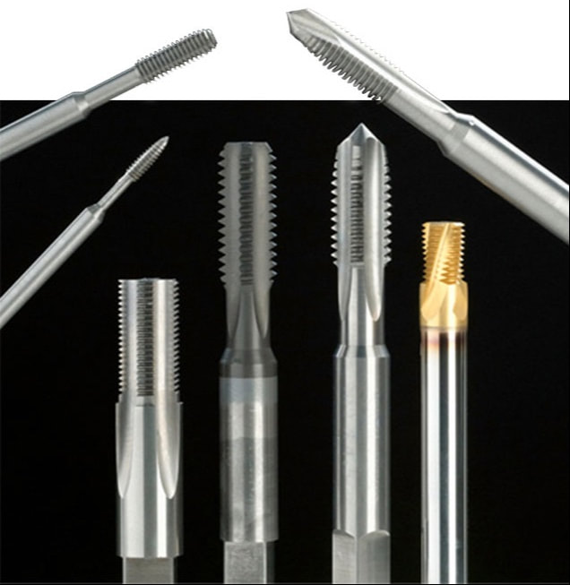
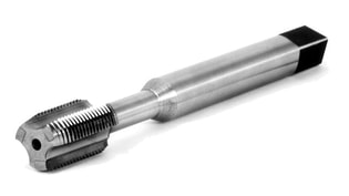
Highly abrasive materials like cast iron, polymers, glass filled polycarbonates, and some cast aluminum are called “hard” materials for a reason. They’re hard to machine, hard on tool life and hard on production cycle times. How do you overcome the difficulties of making parts out of challenging raw stock? By using a tool that’s even tougher. Consider a change from steel taps to carbide taps.
We offer carbide taps in UN and Metric sizes as well as straight and NPT/F Pipe and STI Standards. A wide range of styles and features are available, including straight flute, spiral flute, spiral point, and forming taps. For increased performance and life, we can customize tools with a full line of surface coatings such as TiN, TiCN, and TiALN. How to Use Carbide TapsMachining with carbide does come with some “do’s and don’t”. Hand tapping is generally not recommended. Rigid tapping and spot-on alignment are critical to avoid breakage. Not to worry, however. Modern CNC equipment is ideally suited for carbide applications. Here’s some additional tips. Coolant holes through the taps are an option for flushing chips out of the holes on the most difficult materials like some of the tougher stainless steels and space-age alloys. Carbide STI (Screw Thread Insert) tapping of these materials has become commonplace in the aeronautical and aerospace industries. The Why of Carbide TapsAlthough initially more expensive than HSS taps, significant savings can be realized, especially in long-run jobs. Higher cutting speeds, greater tool life, and reduced downtime from fewer tooling changes translate into reduced machining costs.
An alternative to costly larger sizes is our line of CarbISert® Taps. Solid carbide cutting surfaces are bonded onto a high-speed steel body to provide the best of both worlds; durability of carbide with the “forgiveness” of a steel body and shank. So, don’t let difficult materials give you a “hard” time. Contact us anytime and put our carbide taps to work for you. Watch for Part 2 of this series on carbide taps! Coming in August 2021: The Different Types of Carbide Taps and When to Use Them
1 Comment
In January of this year we welcomed a new member to our Browne & Co. sales team and with manufacturing companies opening up again, it's about time we introduce you to Jeff Terrace!
Just before joining Browne & Co in January 2019, Jeff worked at Hoffmann Group, a German cutting tool, hand tool, workstation and storage solutions manufacturer. Jeff has been working as an InovaTool representative since February of 2019 and recently joined Browne & Company at the beginning of 2020 as our Cutting Tool Specialist. Please send Jeff and email or give him a call to introduce yourself or pick his brain about an application question. North American Tool realizes how confusing the painstaking math is to get preplate part limits and a Tap “H” limit, but don’t worry, all you have to do is contact us with your thread information, and we will do the work. Call us at 800-USA-TAPS. If you want to know how it's done, we’ve included the formulas for the engineer in all of us. If you want to know how it’s done, we’ve included the formulas for the engineer in all of us. When encountering an internal threaded hole requiring it to be plated, it normally needs to be produced oversize to accommodate the plating. There are two methods for determining the correct Tap “H” limit, the “Detailed Method” and the “Simplified Method”. The “Detailed Method” requires you to do more math, but it will also determine the before plate product limits (GO & NOGO) The “Simplified Method” requires less math but will not provide you with the before plate product limits (GO & NOGO) When the plating is applied to the properly oversized threaded hole, the required thread class (2B, 3B) or special PD (pitch diameter) will be met. The effect of plating on a 60° screw thread is a change in PD of 4 times the plating thickness (2 times on each side). That is because the plating itself is parallel to the thread flanks, and the PD is measured perpendicular to the thread axis. As an example, a .0002 plating thickness X 4 results in a PD increase of .0008 (The ratio of 4:1 is for 60° threads only, the ratio for other thread forms such as ACME, 29° is different.) Detailed MethodBefore determining the tap size (H limit), it is necessary to determine the oversize part thread limits first. Once this is achieved, the tap limit is normally position at 40% of the before plate limits. Unfortunately, life is not always easy. The required plating thickness on the print, purchase order, etc. will be expressed in one of two ways, a “Maximum and Minimum Thickness” or a “One Value Thickness” requiring two different ways to calculate the oversize part thread limits. Maximum and Minimum Plating Thickness 1. The Minimum part PD (pitch diameter) is larger by 4 X the Maximum plating thickness 2. The Maximum part PD (pitch diameter) is larger by 4 x the Minimum plating thickness 3. The Tap “H” = a PD that is located at 40% of the before plate limits – minimum after plate limit \ .0005 (“H” limit increment). Selecting the closes “H” limit Example: 1/4-20 UNC-2B, plating thickness, .0002 to .0003 (1/4-20 UNC-2B after plate PD = .2175 – .2224) 1. GO Minimum before coating part PD (pitch diameter) =.2175 (after plate GO or minimum PD) + .0012 (4 X .0003 max plating thickness) = .2187 2. NOGO Maximum before coating part PD (pitch diameter) = .2224 (after plate NOGO or maximum PD) + .0008 (4 X .0002 min plating thickness) = .2232 3. Tap ‘H” Limit .2232 (Maximum before coating part PD) – .2187 (Minimum before coating part PD) = .0045 .0045 X 40% = .0018 .0018 + 2187 (Minimum before coating part PD) = .2205 .2205 (before plate Tap PD) – .2175 (after plate or minimum PD) = .003 0.003 / .0005 (“H” limit increment) = H6 One Value Plating Thickness When a “One Value Plating Thickness” is shown, we establish a maximum and minimum plating thickness values to compute the maximum and minimum before platting thread limits. This is done by assuming that the tolerance on the plating is 50% larger than the “One Value Plating Thickness.” The maximum plating thickness is 6 X, the “One Value Plating Thickness,” and the minimum plating thickness is the same as the “One Value Plating Thickness.” 1. The Minimum part PD (pitch diameter) is larger by 6 X the “One Value Plating Thickness” 2. The Maximum part PD (pitch diameter) is larger by 4 x the “One Value Plating Thickness” 3. The Tap “H” = a PD that is located at 40% of the before plate limits – minimum after plate limit \ .0005 (“H” limit increment). Selecting the closes “H” limit Example: 1/4-20 UNC-2B, plating thickness, .0003 (1/4-20 UNC-2B after plate PD = .2175 – .2224) 1. GO Minimum before coating part PD (pitch diameter) =.2175 (after plate GO or minimum PD) + .0018 (6 X .0003 “One Value Plating Thickness”) = .2193 2. NOGO Maximum before coating part PD (pitch diameter) = .2224 (after plate NOGO or maximum PD) + .0012 (4 X .0003 “One Value Plating Thickness”) = .2236 3. Tap ‘H” Limit .2236 (Maximum before coating part PD) – .2193 (Minimum before coating part PD) = .0043 .0043 X 40% = .00172 .00172 + .2193 (Minimum before coating part PD) = .2210 .2210 (before plate Tap PD) – .2175 (after plate or minimum PD) = .0035 0.0035 / .0005 (“H” limit increment) = H7 Simplified MethodThis method requires knowing what tap “H” limit that is recommended for the thread class of fit (2B 3B etc.) after plating.
Example: The recommended “H” limit for a 1/4 – 20 UNC 2B would be GH5 and for a 3B it would be GH3. Maximum and Minimum Plating Thickness When the plating thickness requirement is given with a maximum and minimum limit you would simply, Example: 1/4-20 UNC-2B, plating thickness, .0002 to .0003 (1/4-20 UNC-2B after plate recommended “H” limit GH5) One Value Plating Thickness When the plating thickness requirement is given with a one value plating thickness limit you would simply, Multiply the plating thickness by 4 (the 60° size change ratio) to determine the PD (pitch diameter) size change in inches. Then divide the PD size change in inches by .0005 (“H” limit increment). The result would be the increase in “H” limit and added to the recommended “H” limit for the required after plate thread class. Example: 1/4-20 UNC-2B, plating thickness, .0003 (1/4-20 UNC-2B after plate recommended “H” limit GH5) .0003 X 4 = .0012 (PD size change in inches) .0012 / .0005 = 2.4 (PD size change in “H” limits) rounder to the closest “H” limit = 2 Recommended “H” limit of GH5 (recommended “H” limit for Class 2B) + 2 = GH7 (pre-plate “H” limit) |
AuthorWe've compiled the latest news and technical information about our principals and our market that we hope you find informative! Archives
August 2024
Categories
All
|