|
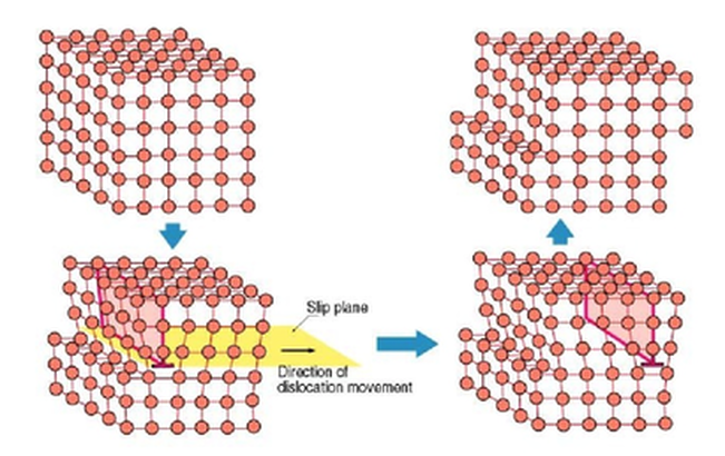
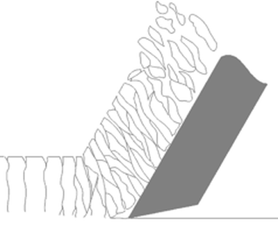
Contrary to popular terminology, metal is not “cut” as much as it is a “forced separation from itself.” To understand this, think of how molecules bond together. Molecules resemble our solar system with the nucleus represented by our Sun (or a carbon atom in the image) and the electrons represent by the various planets. When one molecule “bonds” with another it is as if two solar systems’ planets became intertwined into each others orbits with both solar systems sharing certain planets and making the whole larger than the sum if it’s parts. When we use a cutting tool we are inducing these bonds to break apart. The “machinability” of a particular metal partially defines how easily the material separates from itself. The basic mechanics of forming a chip are the same regardless of the base material. As the cutting tool engages the workpiece, the material directly ahead of the tool is sheared and deformed under tremendous pressure. The deformed material then seeks to relieve its stressed condition by fracturing and flowing into the space above the tool in the form of a chip. The important difference is how the chip typically forms in various materials. Regardless of the tool being used or the metal being cut, the chip forming process occurs by a mechanism called plastic deformation. This deformation can be visualized as shearing. That is when a metal is subjected to a load exceeding its elastic limit. The crystals of the metal elongate through an action of slipping or shearing, which takes place within the crystals and between adjacent crystals. Type 1: Discontinuous ChipCast Iron, Hard Brass and other materials that produce a Powdery chip. “Discontinuous Chip - Discontinuous or segmented chips are produced when brittle metal such as cast iron and hard bronze are cut or when some ductile metals are cut under poor cutting conditions.
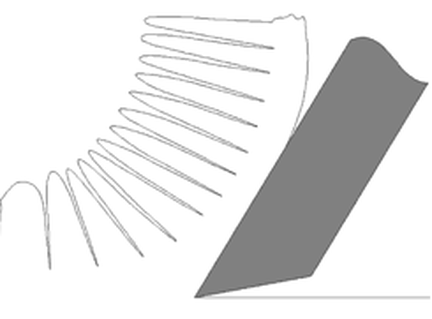
Type 2: Continuous ChipMedium to High carbon and alloy Steels – Long Chipping Materials “Continuous Chip - Continuous chips are a continuous ribbon produced when the flow of metal next to the tool face is not greatly restricted by a built-up edge or friction at the chip tool interface. The continuous ribbon chip is considered ideal for efficient cutting action because it results in better finishes. Unlike the Type 1 chip, fractures or ruptures do not occur here, because of the ductile nature of the metal.”
Type 3: Sheared ChipsLow carbon Steels, Stainless Steels, Nickel Alloys, Titanium, Copper, Aluminum and other soft, “gummy’ Materials. Sheared Chips or as some refer to it “Continuous Chip with a Built-up Edge (BUE). The metal ahead of the cutting tool is compressed and forms a chip which begins to flow along the chip-tool interface.
These metals readily deform in front of the cutting edge and have to be "sheared" by the tool. What the above paragraph doesn’t tell you is that these materials require tools with sharper cutting edges than those used for machining cast Iron or higher carbon content Steels. The chips tend to compress onto the face of the tool which can result in built-up edge.
The chips formed when cutting these metals are thicker than those produced by Medium Carbon or Alloy Steels at the same Feed Rates and Depths of Cut. These thicker chips are stronger and harder to break. Destiny Tool, through a combination of rake face geometry, carbide substrate and concentricity tolerance is able to enable the chip to more readily "separate from itself" which not only improves MRR, but also reduced heat into the end mill and thereby extends tool life as the feed rate increases. High strength metals such as Stainless Steel, Nickel Alloys and Titanium generate high heat and high cutting pressures in the area of the cutting edge. This results in reduced tool life compared to easier to machine materials.
0 Comments
Appears in Print at Production Machining as: 'A Swift Tool Change for Swiss-Type Machines' This coolant-through tooling system replacement for the gang plate on a Swiss-type machine can save hours of spindle downtime per day as well as increase tool life and enhance chip control. While servicing the tools on a traditional platen on a sliding headstock lathe, it can take 10 minutes or more to index one insert. While indexing the tools, coolant spigots can get knocked loose by an operator and can cost a machine shop tool life and time. Once the inserts are indexed, it can take several starts and stops of the spindle for the operator to see if the coolant stream is being directed to where it needs to be.
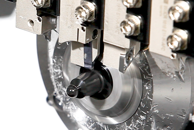
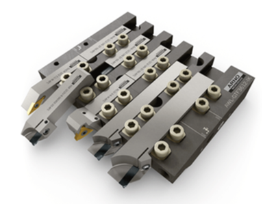
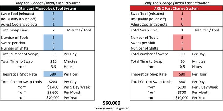
Arno’s Fast Change (AFC) tooling system consists of a gang plate that holds split-shank, coolant-through turning tools, parting tools and grooving tools. Designed like a manifold, the coolant is rerouted through the gang plate to the tools. The UN-style slot in the fixed stop picks up the coolant and runs it through the pipette to the front end where the coolant goes directly to the cutting edge. The AFC system can supply coolant to one port that supports all the tooling positions, or it can supply two ports and divide the tooling positions with the needle valve. The tooling system only needs to be plumbed once and, according to the company, after that, a high-pressure coolant line should not need to be touched again. With proper setup, the high-pressure lines are moved behind the machine guards, creating a clean machining environment. This enables operators to complete safer routine maintenance. Also, the AFC’s low-profile clamps do not collect as many chips compared with a typical clamping system. When replacing a split-shank tool, the operator simply loosens two clamps to remove the cutting head and then replaces it with a new one, the company says. Simple, Quick FunctionalityA Time and Money SaverUsing the AFC system, Arno reports that it takes 17 seconds to change a tool, a vast improvement to the typical 7 to 10 minutes it can take using a traditional gang plate. The conventional method might take five minutes to change a tool, a minute to touch the tool off and another minute to adjust the spigot, for instance.
In comparison, when an operator is working with the AFC system, retouch is not necessary because the tool will repeat within plus or minus a thousandth of the previous tool positions. There is also no need to factor in time for readjusting coolant lines because the new system is a true, coolant-through system. It is also not necessary to factor in the clearing away of chips because those surfaces have mostly been eliminated with the smooth AFC design, according to Stroup. Therefore, the 17-second tool change time is the only time to factor in. But, for a real-world example, he increases the time to one minute to consider a distracted operator that might use extra seconds Although there are still 30 idle times per day, there are now only 30 minutes of downtime per day instead of 210 minutes using the traditional gang plate. “That only costs $10,000 per year, which means you’ve just made $60,000 a year on that one spindle by adopting the AFC system,” Stroup says. |
AuthorWe've compiled the latest news and technical information about our principals and our market that we hope you find informative! Archives
June 2024
Categories
All
|
|
Browne & Co., Inc.
9605 Tanager Drive Chardon, Ohio 44024 |
© 2024 Browne & Co., Inc. All Rights Reserved
web design by Rapid Production Marketing |

 RSS Feed