|
Contrary to popular terminology, metal is not “cut” as much as it is a “forced separation from itself.” To understand this, think of how molecules bond together. Molecules resemble our solar system with the nucleus represented by our Sun (or a carbon atom in the image) and the electrons represent by the various planets. When one molecule “bonds” with another it is as if two solar systems’ planets became intertwined into each others orbits with both solar systems sharing certain planets and making the whole larger than the sum if it’s parts. When we use a cutting tool we are inducing these bonds to break apart. The “machinability” of a particular metal partially defines how easily the material separates from itself. 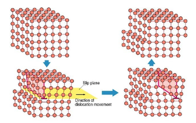 The basic mechanics of forming a chip are the same regardless of the base material. As the cutting tool engages the workpiece, the material directly ahead of the tool is sheared and deformed under tremendous pressure. The deformed material then seeks to relieve its stressed condition by fracturing and flowing into the space above the tool in the form of a chip. The important difference is how the chip typically forms in various materials. Regardless of the tool being used or the metal being cut, the chip forming process occurs by a mechanism called plastic deformation. This deformation can be visualized as shearing. That is when a metal is subjected to a load exceeding its elastic limit. The crystals of the metal elongate through an action of slipping or shearing, which takes place within the crystals and between adjacent crystals. Type 1: Discontinuous ChipCast Iron, Hard Brass and other materials that produce a Powdery chip. “Discontinuous Chip - Discontinuous or segmented chips are produced when brittle metal such as cast iron and hard bronze are cut or when some ductile metals are cut under poor cutting conditions.
Type 2: Continuous ChipMedium to High carbon and alloy Steels – Long Chipping Materials “Continuous Chip - Continuous chips are a continuous ribbon produced when the flow of metal next to the tool face is not greatly restricted by a built-up edge or friction at the chip tool interface. The continuous ribbon chip is considered ideal for efficient cutting action because it results in better finishes. Unlike the Type 1 chip, fractures or ruptures do not occur here, because of the ductile nature of the metal.”
Type 3: Sheared ChipsLow carbon Steels, Stainless Steels, Nickel Alloys, Titanium, Copper, Aluminum and other soft, “gummy’ Materials. Sheared Chips or as some refer to it “Continuous Chip with a Built-up Edge (BUE). The metal ahead of the cutting tool is compressed and forms a chip which begins to flow along the chip-tool interface.
These metals readily deform in front of the cutting edge and have to be "sheared" by the tool. What the above paragraph doesn’t tell you is that these materials require tools with sharper cutting edges than those used for machining cast Iron or higher carbon content Steels. The chips tend to compress onto the face of the tool which can result in built-up edge.
The chips formed when cutting these metals are thicker than those produced by Medium Carbon or Alloy Steels at the same Feed Rates and Depths of Cut. These thicker chips are stronger and harder to break. Destiny Tool, through a combination of rake face geometry, carbide substrate and concentricity tolerance is able to enable the chip to more readily "separate from itself" which not only improves MRR, but also reduced heat into the end mill and thereby extends tool life as the feed rate increases. High strength metals such as Stainless Steel, Nickel Alloys and Titanium generate high heat and high cutting pressures in the area of the cutting edge. This results in reduced tool life compared to easier to machine materials.
0 Comments
by Steven Oszust Jr. at Fullerton Tool  This month we will focus on one of our most successful legacy tools, the Fullerton Tool's 3400 Harmon-i-Cut end mill. Nearly two decades ago, we recognized the advancements in machining technology demanded increasingly aggressive machining operations to enhance productivity and reduce production costs.
Advancements in spindle technology enabled greater spindle speeds while maintaining the necessary power to perform more aggressive cutting operations. With the greater acceptance and application of high-speed machining (HSM) practices in programming, spindle speeds were increased to a range which was greater than those traditionally used for an increase in material removal rates (MRR) over traditional tools. High-speed machining is achieved by increased axial depth of cut and higher spindle speeds, combined with constant chip loads requiring new high-performance tooling design. One limitation in achievable MRR is self-excited vibrations of the cutting tools, known as chatter. Chatter is caused by variations in the inconsistent chip thickness caused when the vibration of the tooth currently engaged in the cut is out of phase with the vibration of the previous tooth. Specifically engineered geometries greatly reduce chatter leading to smoother running, faster feed rates. These tools are ideal for all roughing and finishing operations, offering longer tool life and improved surface finishes. Harmon-i-cut end mills have engineered flute shape designed for maximum rigidity, variable helix, variable rake, superb chip evacuation, and excellent shearing action. Reduced load pressures and super stiff design promotes less chatter, achieving rapid Harmonic-free stock removal at rates never seen before. By utilizing chip thinning strategies, significant increases in productivity and tool life can be achieved. These methods are also helpful when using machines with less power and stability. Even with weaker machines and less stable working conditions, very high cutting parameters can be achieved. These strategies are particularly effective for increasing process reliability in difficult to machine materials or challenging applications. Consider Fullerton Tool's 3400 series Harmon-i-cut a cut above the rest. With our vast inventory of sizes and configurations, we can provide a solution for your needs. Contact Browne Sales to get started In January of this year we welcomed a new member to our Browne & Co. sales team and with manufacturing companies opening up again, it's about time we introduce you to Jeff Terrace!
Just before joining Browne & Co in January 2019, Jeff worked at Hoffmann Group, a German cutting tool, hand tool, workstation and storage solutions manufacturer. Jeff has been working as an InovaTool representative since February of 2019 and recently joined Browne & Company at the beginning of 2020 as our Cutting Tool Specialist. Please send Jeff and email or give him a call to introduce yourself or pick his brain about an application question. Article originally published in Cutting Tool Engineering. By, David Conigliaro March 1, 2014 - 10:45am The well-established concept of radial chip thinning (RCT) provides compelling productivity-enhancing benefits, but is still not widely applied. RCT occurs when the DOC is less than the radius of a round milling insert and chip thickness is less than the programmed feed per tooth. This means a higher programmed feed rate is needed to achieve a particular chip thickness, measured in ipt. In other words, the programmed feed rate can be higher because of chip thinning. Many programmers and machinists are afraid to increase the feed, a fear usually based on an unfortunate previous experience. However, the industry trend is to step-down significantly deeper during machining, greatly reducing step-over. Step-overs have been typically much more than 50 percent of a tool’s width because end users tend to take shallow step-downs, whereas deep step-downs require reduced step-overs. It’s important to note RCT doesn’t comes into play when applying less than half the tool’s width.
Toolpaths programmed with Mastercam’s Dynamic Machining suite produce radial chip thinning (top), whereas a traditional toolpath (above) doesn’t enable the productivity-enhancing benefits RCT provides. New CAM toolpaths and cutting tool designs, such as those used in Mastercam’s Dynamic Machining suite and Iscar’s High-Efficiency Machining tools, push the advantages of RCT to its practical limit. None of this was possible until all the elements—including cutting tools, machine tools and CAM toolpaths—caught up to each other a few years ago. Therefore, now is the time to consider RCT for your operations. Variable-pitch tools, in particular, have virtually eliminated harmonics during machining, and advances in tool coatings enable them to withstand temperatures up to 900° F (482° C). In addition, machine tools are faster and CAM toolpaths are producing movements conducive to full-depth cutting. On the CAM side, local resellers can demonstrate how to gain efficiencies. As a result, machine shops are applying RCT to improve productivity 30 to 200 percent by reducing cycle times. They are also reducing costs via longer, more predictable tool life and less wear and tear on machine tools. For example, one of our customers was consuming 70 minutes cutting pockets in mold bases. It was taking shallow step-downs and aggressive step-overs while running at high feed rates. We exchanged their tool with an Iscar tool made of higher-quality carbide designed for high feeds and reduced cycle time to 45 minutes. Next, we applied the Dynamic Machining toolpath calculations—stepping all the way down—and replaced the customer’s traditional roughing operation. Time to cut the pockets fell to 12 minutes, an improvement of nearly 500 percent. The combination of changing the tool and its motion also reduces tool cost per part, because tools last longer. Another money-saving aspect with these advanced machining techniques is coolant isn’t usually required for heat removal when cutting most steels if the speeds and feeds are correct. Instead, chips are simply air-blasted away. Dry machining actually extends tool life, because the heated tool is not being shocked when coolant repeatedly hits it, which breaks down the coating and causes premature tool failure. It’s challenging for shops to try new approaches when the daily routine demands shipping high-quality work and current machining methods are achieving that. However, shops can do even better. All it requires is a conversation with your CAM reseller and tool vendor. While the science of RCT can be confusing, the application is not. When the step-over is more than 45 percent, the productivity improvement will be modest. But the cycle-time reductions can be amazing when the step-over ranges from 10 to 35 percent. Remember, new dynamic toolpaths ensure the machine will not shove a tool into a part corner or have it do a full-width cut. Give it a try!
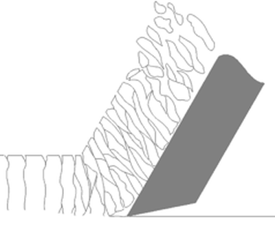
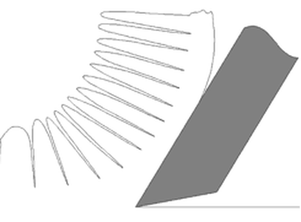
 Written by: Jonathan Maes Originally Published on "Make it from Metal" Jonathan has been working in manufacturing and repair for the past 12 years. His specialty is machining. He manages a machine shop with multiaxis CNC machines for aerospace and medical prototyping and contract manufacturing. Trochoidal Peel Milling Toolpath In the previous article, A Machinist’s Guide to Trochoidal and Peel Milling: Part One, peel milling was used to clear out easily accessed material. But what if you need to cut a deep slot? Can you still use the principles of peel milling? Definitely. This is where trochoidal peel milling comes in. To begin, let’s look at what a trochoid is. The Trochoid Here’s the basic concept of a trochoid: Imagine swinging a weight over your head at the end of a rope while you walk forward. That basic motion of a point rotating around a center and moving forward is a trochoid. Here’s an illustration of the motion: 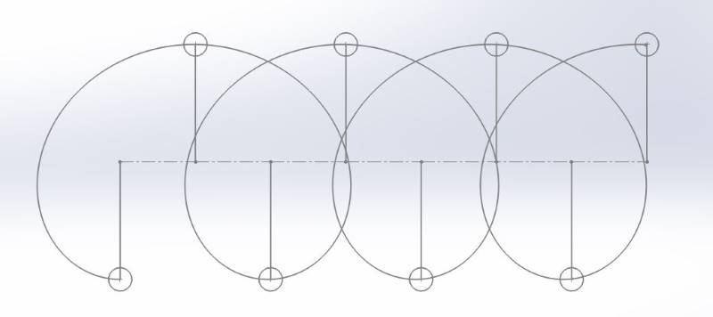 Trochoidal motion – the point is spun as the center point advanced. What you essentially get is a carving motion. For toolpaths, the forward advancement is low, but the “spinning” motion is done at high speeds. This is what keeps the cutting pressure light. Here’s an example of what one of these toolpaths looks like in a CAM system: 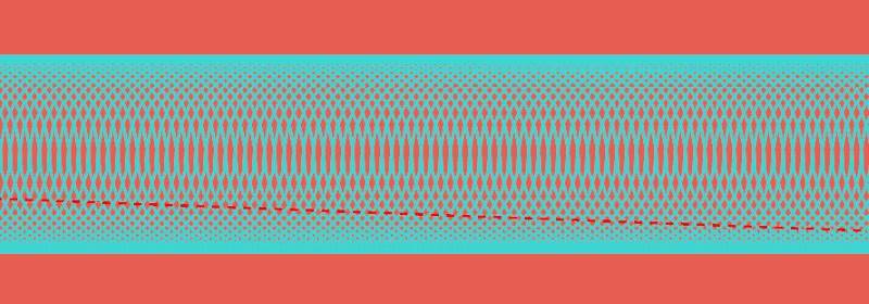 Trochoidal toolpath As you can see there, rapidly feeding the tool forward with sweeping motions can maintain a consistent radial engagement. Chip Clearance Trochoidal milling is a really effective approach for tight areas where chip clearance would be an issue. With traditional milling, it can be difficult to evacuate thick, heavy chips from deep features like pockets. This means that these chips will be cut again as the tool feeds around within the feature. This additional, uncontrolled cutting of metal chips not only adds substantial wear and tear on the cutting tool, but it also adds instability to the operation. A buildup of chips can unexpectedly snap the cutter in half. Trochoidal milling is an excellent way of clearing chips out of deep features. Instead of the thick, heavy chips of conventional milling, chips from peel milling are long, slender and light. That means that coolant pressure or an air blast can easily clear them away from a workpiece. 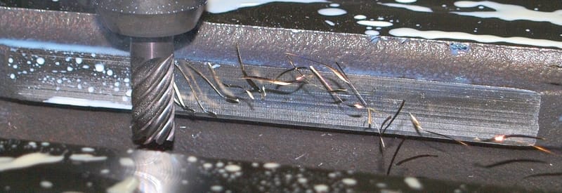 Peel milling chips are thin and light One thing worth noting, though, is that peel milling chips are made really fast. This means that your coolant or air pressure needs to be very reliable. If there are any hiccups in delivery, things will go south fast. What’s Required for Peel and Trochoidal Milling? I know a lot of guys that have tried this with standard tools that are intended for traditional machining. Then when something blows up, it’s (in their opinion) because peel milling is a gimmick and doesn’t work. I can assure you that it works very well, but you need to make sure that you’re using the right tools and equipment. Tool HoldersPeel milling puts a lot more pressure on the tool, and has the potential of being a nightmare for vibration. Your tool holder needs to be really solid to be able to handle this high performance milling. What does this mean? Don’t use weldon shank or ER collet end mill holders. Seriously, you will pretty well never have great results with these. They just don’t hold the tool firmly enough and dampen vibration. Even if you use a 48″ cheater bar. Aside from the really high speeds and feeds that you’ll achieve with peel milling, tools have a tendency of pulling out. This is because the teeth are hitting the workpiece so aggressively that the helix of the flutes will push the cutter down and out of the tool holder. Weldon shank holders and ER collets do very little to resist this. My favorite option for this is a good quality hydraulic tool holder, although I’ve also had very good success with shrink fit systems. What I like about the hydraulic tool holders is their versatility and vibration dampening qualities. They don’t have the tendency to ring at certain frequencies like other systems do. And, to fit up an endmill of a different diameter, you only need to change the sleeve. Shrink fit systems are also excellent. The clamping force of the steel body once cooled down is insane, so tools clamped in this way are really rigid. The disadvantage to this is that you need a system for heating the holders up to change the endmills. This can be a pretty hefty startup cost, so it’s a bit of a commitment for shops to gain this capability. Specialized Cutters Here’s another interesting aspect of peel milling: The chips are always slender and thin. We can use this to our advantage when it comes to cutter selection. This isn’t so much an absolute requirement, but it will help you take advantage of the high performance capabilities of peel milling. The traditional approach of thick, heavy cuts meant that the tools needed a large amount of space between flutes for chip clearance. These chips needed somewhere to go, so large gaps needed to be designed into these cutting tools to accommodate them. With peel milling, you don’t need that massive chip clearance. What this means is that two things are possible:
Now considering the example we had mentioned before comparing traditional vs peel milling, we can see that with specialized tools, we can get significantly more efficiency out of peel milling. This is why many shops have been able to double their material removal by investing in specialized equipment. High Speed Mills If you have a tired, old machine from the ’80’s, you might not be too impressed with it’s interpretation of peel milling. Especially for things like trochoidal milling, you need a fast machine. And not just maximum feed rates, either. A machine needs to be able to handle hard acceleration and deceleration, or else you’ll never get up to speed. You might notice on your machine that when you’re doing tight corners, the feed rate that’s displayed on the controlled is often constantly changing, slowing down on sharp turns. Your mill needs to be able to make small, fast movements accurately. For most machines, you can punch in a line of code that will change the modes – from high speed mode to exact stop mode and everything in between. In high speed mode, it needs to be able to honor the programmed toolpath without significantly overshooting. Otherwise, you’ll have a lot of broken tools when your machine ends up overshooting and pushing your tool 0.080″ into the material instead of the intended 0.050″. Aside from having fast, responsive servos to handle sharp changes in direction quickly, your machine needs to be a fast thinker. For high speed machining, you might end up with programs with millions of lines of code. If your machine controller can’t read the code fast enough, then all your potential efficiency from peel milling will be lost while your machine tries to figure out its next move. Machines that are well equipped for high speed machining will advertise a high “block look-ahead”, often something to the tune of 10,000 blocks. What this means is that the controller will read 10,000 blocks ahead of the current block to be able to “plan out” the most efficient way of hitting this toolpath within the allowable tolerance. If your machine doesn’t have this ability, then you might find that your feed rate never actually hits what you programmed it to be. Cam System This is fairly straightforward. In order to benefit from peel milling, you need to have software that is capable of it. The good news is that peel milling has been around for a while, so the large majority of decent CAM packages will have something to offer. They’re not all created equal, though. Some allow you to have a tighter control than others. If you’re looking at a CAM package for your shop, take your time and see how good both the CAM toolpaths and the postprocessed results are. The reason that I say to pay attention to the postprocessor is that with peel milling, you will have a lot of small movements. You want this to be calculated accurately as arc commands (or splines if your machine has a Siemens controller) without rounding issues. If you have to resort to using G1 line motions because you keep getting errors on your machine controller saying that there’s a problem with your G2 and G3 values, you won’t be a happy camper. Really, this is becoming less and less as a factor as peel milling becomes more mainstream, but even still, it’s a factor to pay attention to. When is Peel Milling Practical? There’s a reason that this isn’t the only operation you can select in your CAM software: while it is a great solution, it can’t be applied to everything. Peel milling works best when you can really sink your tool deep in the material. In other words, if you’re doing shallow pocketing, you’ll be better off with another strategy. Slotting Trochoidal milling is very often the best solution for slotting, but again it really does depend on the feature geometry. For example, the slot might be so deep that the only reasonable way of cutting it is either with a slitting saw or an EDM. If the slot is 0.050″ wide x 1.000″ deep, no endmill will help you. I find the sweet spot for trochoidal slotting to be where you can maximize the depth of an endmill that’s between 50-75% of the slot width. In other words, a half inch endmill with a trochoidal toolpath will be an excellent choice for a slot that’s 0.75″ wide and 1.000″ deep. Pocketing This is an excellent choice for deep pockets. The thin, light chips are easily blasted out of the pocket with and air blast or high pressure coolant, and the material removal rate is very high if you can use the full flute length. Hard or Exotic Materials When I’m roughing titanium, I use one of two methods: plunge milling or peel milling. The material removal rates of plunge milling in titanium are second to none, but the leftover scallops can be a pain to clear out. They often require an excess of semi-finishing operations before you can run your finishing tool to complete the feature. Peel milling, on the other hand, can often rough and finish in a single operation. Especially for deep and narrow features, it’s hard to beat. Peel milling really shines when it comes to hard and abrasive materials. Since it distributes wear along the entire flute length, it can be a great solution in applications where notch wear or chipping is common. Here are some materials where you should seriously consider using peel milling as a practical way of roughing:
When Peel Milling Doesn’t Make Sense When you can’t use a good amount of your flute length, then peel milling probably isn’t a great option.
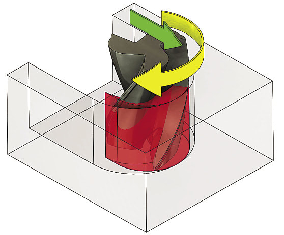
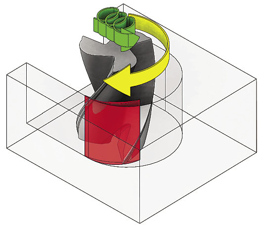
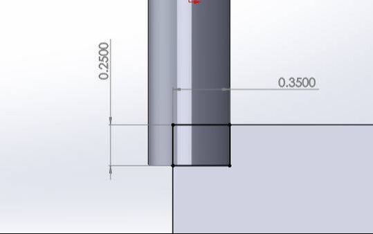
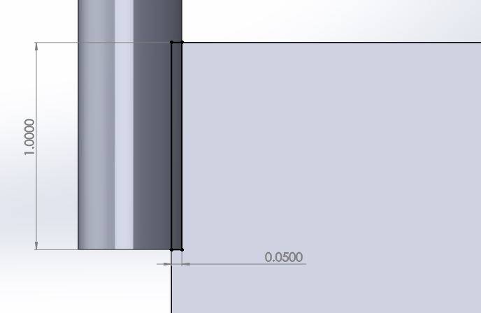
For example, if you have a shallow slot – let’s say 0.750″ wide x 0.375″ deep – you’ll be better off going the traditional route of using a 3/4″ endmill and burying it. If it’s an exotic or hardened material, peel milling might make sense even if you can’t use much flute length. Sometimes the solution is to simply use a smaller cutter. Or look into other strategies like hi-feed cutting (low Z depth, full cutter width stepover, and very high feed). Ultimately, you’ll get a good feel for it once you’ve tried it a bit. Maybe try programming the toolpaths a few different ways and see which one seems to be able to achieve the best cycle times. Just make sure that your machining conditions are set appropriately for each strategy – don’t use standard feed rates for peel milling. There you have it, you’re ready to take on the peel milling world. Do you have any tips and tricks for high speed machining? Or do you have any questions about peel milling? Share them in the comments below!  Written by: Jonathan Maes Originally Published on "Make it from Metal" Jonathan has been working in manufacturing and repair for the past 12 years. His specialty is machining. He manages a machine shop with multiaxis CNC machines for aerospace and medical prototyping and contract manufacturing. This is the first of a two part series. This part will discuss the fundamentals of Trochoidal and Peel Milling and the next part will discuss what is required for Peel and Trochoidal Milling covering toolholders, cutting tools and cam systems 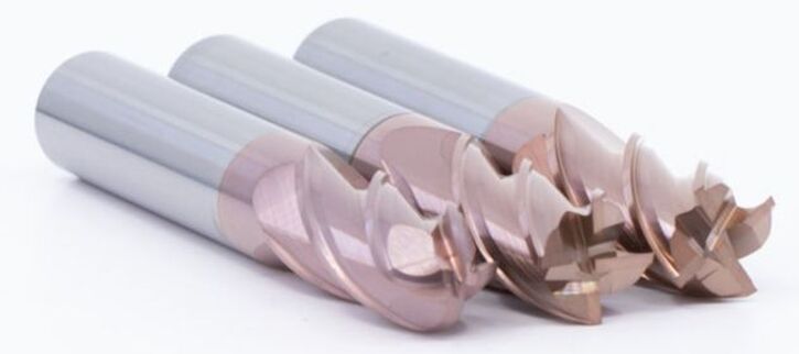 Fullerton Fury 3500 End Mill is ideal for Trochoidal and Peel Milling All the aspects of high speed machining can be a real challenge to wrap your head around. Filtering through what’s real and what’s just a buzzword can be a chore in and of itself. So is peel milling a technique worth learning? Definitely. Peel milling is an approach that uses high feed rates, low radial depth of cut and high axial depth of cut. It relies heavily on the principle of chip thinning, using a tool path that maximizes tool wear along the entire flute length. Trochoidal peel milling is a particular type of motion – a circular high speed maneuver that is excellent for carving out deep slots and other narrow features. Ok, that was pretty packed with information. Let’s break that up and use a few diagrams to explain what’s going on, how to do it properly, and how to know when your application justifies it. Peel Milling Principles The basic idea here is to use a small stepover, usually around 10% of the tool’s diameter, but max out the Z depth. Of course, when using this method in the real world, you’re best off consulting the cutting tool manufacturer for recommended cutting parameters, but these numbers are usually pretty realistic. For example, if you have a 0.500″ endmill, you’ll cut at a depth of 1.0″ but with a stepover of 0.050″. Compare that to a standard approach of cutting with a depth of 0.250″ and a stepover of 70%, or 0.350″. 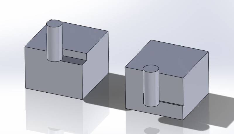 Traditional milling vs. Peel Milling. Compare a 0.500″ endmill performing a Traditional milling approach of cutting with a depth of 0.250″ and a stepover of 70%, or 0.350″ on the left to Peel Milling with a depth of cut of 1.0″ and a stepover of 0.050″on the right. Now if we look at the area of cutting engagement, we can work out what kind of stock removal we can get. For the standard milling approach, we’re cutting an area that’s 0.250″ x 0.350″, or an area of 0.0875 square inches.
For the peel milling approach, we’re cutting an area that’s 0.050″ x 1.000″, or 0.050 square inches. At this point, it’s not too impressive, is it? Peel milling doesn’t have nearly the same engagement as the traditional approach. But there’s a secret sauce. Peel milling can take advantage of something called chip thinning. If you take a look at the size of chip that you get with such a low radial engagement, you’ll realize that it’s actually super thin. What this means is that you can crank up the feed rate to get a normal chip thickness.
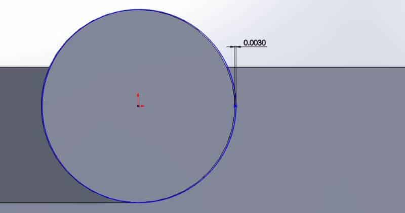
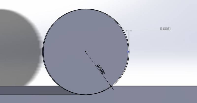
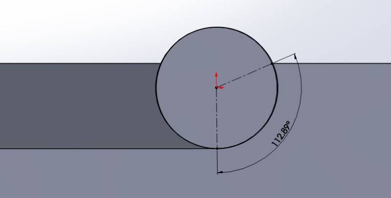
According to those sketches, you can cut the material with a 70% higher feed rate and have the same chip thickness as the “traditional machining” model. Now let’s convert those previous examples from 2D area to 3D volume. To do this, we’ll need to add some material data to come up with realistic feed rates. Let’s say that we’re cutting 4140 HTSR. We’ll use a cutting speed of 400 SFM for standard machining. Let’s see what that stock removal looks like. For conventional machining, the RPM works out to 3200 RPM. We’ll use a feed rate of 0.003″ per tooth, using a standard 4 flute endmill. This means that we’ll be feeding the cutter at 38.4 inches per minute. Taking that same cut of 0.250 deep x 0.350 stepover, our 2D cut is 0.0875 square inches. To convert that to cubic inches per minute, we’ll multiply that by our feedrate. 0.1875 square inches x 38.4 inches per minute = 3.36 cubic inches per minute. Now let’s compare that to peel milling. To maintain the same 0.003″ chip thickness at 0.050″ stepover, the feed can be increased to 0.0051″ per tooth. Another perk of peel milling is that the RPM can also be bumped up. So let’s increase that RPM to 500 SFPM, using a 0.0051″ chip per tooth. This works out to 4000 RPM, and a feed rate of 81.6 IPM. As mentioned previously, the 0.050″ stepover and 1.000″ depth of cut works out to an area of 0.050 square inches. 0.050 square inches x 81.6 inches per minute = 4.08 cubic inches per minute. That’s about 15% faster material removal than the traditional approach. But the advantages of peel milling don’t end there. Maximizing Tool Wear One of the real disadvantages of the traditional roughing approach is that wear is very concentrated to the bottom of the end mill. Using that same previous example, what would our endmill look like after an hour of work? The bottom 0.250″ would be worn out, and the top 0.750″ would be totally fresh. Not really maximizing the use of the tool, is it? Now aside from the cost of the endmill itself, add the down time of the machine operator swapping the tool for a fresh endmill. Overall, it’s just not an efficient method. Now compare that to the tool that’s used for peel milling. What would that tool look like after an hour? Instead of all the wear focused on 25% of the tool, the wear would be evenly distributed across the entire flute length. Also, because of the small radial engagement, the individual flutes are actually in the cut for less time. Let me illustrate.
To put it simply, the actual working time of the cutter’s flutes is about 1/3 of the time for peel milling compared to traditional milling. Does this mean that your cutters last 3x as long? Not always, in my experience. But I do tend to improve tool life noticeably, especially in hard to machine materials like titanium, inconel and cobalt chrome. Check back for the next installment: What’s Required for Peel and Trochoidal Milling? In the next article, Jonathan will discuss Trochoidal Peel Milling Toolpaths and what is required for Peel and Trochoidal Milling covering toolholders, cutting tools and cam systems. Check back soon!
|
AuthorWe've compiled the latest news and technical information about our principals and our market that we hope you find informative! Archives
June 2024
Categories
All
|


 RSS Feed
|
Browne & Co., Inc.
9605 Tanager Drive Chardon, Ohio 44024 |
© 2024 Browne & Co., Inc. All Rights Reserved
web design by Rapid Production Marketing |