|
Everede boring bars apply full-section shank geometry, controlled coolant hole sizing, increased braze surface area, and minimized insert projection to maintain rigidity and stability under cutting load. Everede Tool Company boring bars are engineered to maintain stiffness, braze integrity, and dimensional stability under cutting load. Each construction element is intended to preserve cross-sectional strength and minimize deflection at the cutting edge.
Shank Configuration and Flats Series A–D bars are manufactured without flats as standard. Eliminating flats preserves full shank diameter, increasing the second moment of area and improving resistance to bending. ANSI-style bars may include one or two flats by diameter when required for set-screw retention. Flat width is limited to what is necessary for clamping force while maintaining structural integrity. Clamp-sleeve mounting maintains full circumferential support of the shank and provides the highest achievable rigidity. Result – Increased stiffness and improved resistance to deflection under radial cutting forces. Internal Coolant Hole Geometry Coolant holes are drilled to a diameter-specific size that is smaller than many competing designs. Reducing internal bore diameter increases remaining wall thickness and improves bar rigidity. The coolant passage delivers flow directly to the cutting zone while preserving strength through the neutral axis. This supports longer diameter-to-length ratios without increasing vibration risk. Result – Higher structural stiffness with controlled coolant delivery at extended overhangs. 20° Cone Angle at the Insert Pocket The insert pocket incorporates a 20° cone interface between the carbide head and steel shank. This geometry increases effective brazed surface area and distributes load over a larger bonded interface. The increased brazed area improves load transfer and reduces localized stress concentrations during cutting and interrupted engagement. Result – Improved braze joint strength and reduced risk of braze failure. Insert Projection Length The distance from the bar face to the cutting edge is minimized. Shortening this unsupported length reduces the bending moment applied to the bar during cutting. Lower bending moment improves stability and reduces vibration amplitude at the insert. Result – Increased cutting stability and improved dimensional consistency. Combined Structural Effect The combined effect of full-diameter shanks, reduced internal bore size, increased braze surface area, and minimized insert projection produces a boring bar optimized for rigidity. These construction elements support stable performance at longer overhangs and higher cutting loads across a wide range of boring operations. Do you hae questions? Contact the team at Browne & Co. to answer them!
0 Comments
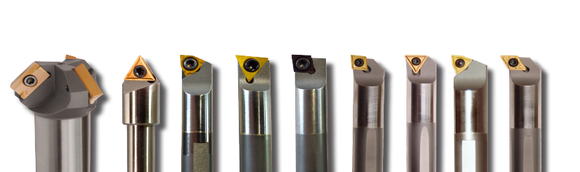
Choosing the right insert for boring applications is critical for optimizing performance, achieving desired surface finishes, and extending tool life. The insert's geometry, material composition, and coating determine its cutting behavior, wear resistance, and suitability for specific materials and machining operations. Understanding the characteristics and applications of insert types allows you to make informed decisions that improve efficiency, productivity, and overall outcomes in your machining processes. This short guide aims to provide a comprehensive overview of insert types compatible with Everede boring bars and how their distinctive features contribute to profitable machining. Everede boring bars accept a selection of standard carbide inserts. Understanding how and why certain style so inserts are sued for the different types of bars will help you improve tool life and finish. Everede offers inserts in the following geometry: CDCD, TDGB-3, TDGH-3, & TDGC, TPGB-3, TPGH-3, & TPGC-3 and WCGT (Trigon) Inserts. As you already know, the ANSI and ISO insert designation systems provide a standardized way to describe the shape, angle, and other attributes of cutting inserts used in machining operations. The first letter of the insert code indicates the shape of the insert, while the second letter refers to the clearance angle. Here's how CD, TD, TP, and WC (Trigon) style inserts compare based on these designations: CD Style Inserts
DC Style Inserts
TD Style Inserts
TP Style Inserts
WC (Trigon) Style Inserts
VC Style Inserts
In summary, the choice between CD, TD, TP, and WC style inserts depends largely on the specific requirements of the machining operation, including the bore size, material hardness, and the desired balance between cutting edge strength and clearance angle.
CD and TD inserts, with their 15-degree clearance angle, are more suited to applications requiring a high degree of clearance to avoid dragging in smaller diameters. In contrast, WC inserts, with their 6 cutting edges and 7-degree clearance angle, offer enhanced cutting edge strength for heavier cuts in larger diameters, although they provide less clearance. TP inserts strike a balance with an 11-degree clearance angle, offering a compromise between clearance and edge strength. As a final note, please keep in mind that Everede boring bars also often have the insert seated in a pocket that may enhance the clearance angle. For more information please contact Browne & Co to set up a call to answer your questions. Four, Six, Eight, Steel, Heavy Metal, Carbide: The Fundamentals of Selecting the Correct Boring Bar2/11/2025 Boring bars are indispensable tools for enlarging and refining holes, a critical step in the machining process. They come in various types, each designed to address specific machining needs. Selecting the correct boring bar for use in your your turning application can make your life a lot less stressful. Cutting Forces During Boring Operations During boring operations, the tool encounters forces that can impact its effectiveness. Primarily, tangential and radial cutting forces exert downward and lateral pressure on the tool, potentially causing deflection away from the workpiece. The Impact of Radial Force Radial force plays a significant role, especially in scenarios with excessive tool overhang. This force can push the insert away from the cutting surface, leading to deflection and chatter. The extent of this deflection correlates directly with the tool's overhang, depth of cut, and feed rate. Minimizing overhang is crucial to mitigate these issues, ensuring stability and precision. Tangential Force Dynamics Tangential force, on the other hand, tends to displace the tool downward and outward, away from the workpiece's centerline. This displacement can compromise the tool's clearance angle, critical for maintaining the quality of the cut. When boring small diameter holes, maintaining a sufficient clearance angle is paramount to prevent the tool from making unintended contact with the hole's interior walls, preserving the integrity of the bore. Some Recommendations for Optimal Performance
By understanding and addressing the implications of tangential and radial forces, machinists can enhance the accuracy, finish, and overall success of boring operations. These adjustments not only improve tool performance but also extend tool life and enhance workpiece quality. Selecting the Shank DiameterSelecting the right shank diameter is crucial, and it involves evaluating the minimum machining diameter of the boring bar alongside the desired bore diameter. Optimal selection dictates choosing a shank diameter that is as large as possible. Nevertheless, it's essential to exercise caution, as a shank diameter that is too close to the bore diameter will lead to chip control at least and chip packing at worst. Consequently, the choice of shank diameter should be tailored to the specific application requirement while leaving enough room for your chips to evacuate. Remember, if you're roughing you're going to be taking a bigger bite than you are if you are finishing. A couple decades ago, I was having some issues with chip packing that I couldn't solve. I called in my cutting tool specialist, Charles Colerich. Charles took one look at the application and said "Just turn the bar upside down. Gravity works." No one ever said the insert needed to be facing upwards. As a result, instead of the chips trying to evacuate over the top of the bar, the coolant washed them under the bar. Sometimes the best thing to do is step back and look at the problem in its simplest terms and apply some common sense. When he told the machinist to turn the bar over the shop foreman and I looked at each other and both had facepalm moment "why didn't; we think of that" together. Selecting the Correct |
AuthorWe've compiled the latest news and technical information about our principals and our market that we hope you find informative! Archives
February 2026
Categories
All
|


RSS Feed