
Contrary to popular terminology, metal is not “cut” as much as it is a “forced separation from itself.” To understand this, think of how molecules bond together. Molecules resemble our solar system with the nucleus represented by our Sun (or a carbon atom in the image) and the electrons represent by the various planets.
When one molecule “bonds” with another it is as if two solar systems’ planets became intertwined into each others orbits with both solar systems sharing certain planets and making the whole larger than the sum if it’s parts.
When we use a cutting tool we are inducing these bonds to break apart.
When one molecule “bonds” with another it is as if two solar systems’ planets became intertwined into each others orbits with both solar systems sharing certain planets and making the whole larger than the sum if it’s parts.
When we use a cutting tool we are inducing these bonds to break apart.
The “machinability” of a particular metal partially defines how easily the material separates from itself.
The basic mechanics of forming a chip are the same regardless of the base material. As the cutting tool engages the workpiece, the material directly ahead of the tool is sheared and deformed under tremendous pressure. The deformed material then seeks to relieve its stressed condition by fracturing and flowing into the space above the tool in the form of a chip.
The important difference is how the chip typically forms in various materials.
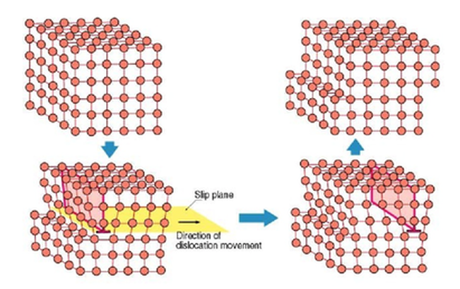
Regardless of the tool being used or the metal being cut, the chip forming process occurs by a mechanism called plastic deformation. This deformation can be visualized as shearing. That is when a metal is subjected to a load exceeding its elastic limit.
The crystals of the metal elongate through an action of slipping or shearing, which takes place within the crystals and between adjacent crystals.
The important difference is how the chip typically forms in various materials.
Regardless of the tool being used or the metal being cut, the chip forming process occurs by a mechanism called plastic deformation. This deformation can be visualized as shearing. That is when a metal is subjected to a load exceeding its elastic limit.
The crystals of the metal elongate through an action of slipping or shearing, which takes place within the crystals and between adjacent crystals.
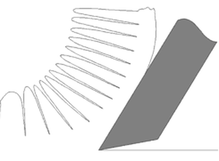
Type 1: Discontinuous Chip
Cast Iron, Hard Brass and other materials that produce a Powdery chip.
“Discontinuous Chip - Discontinuous or segmented chips are produced when brittle metal such as cast iron and hard bronze are cut or when some ductile metals are cut under poor cutting conditions.
“Discontinuous Chip - Discontinuous or segmented chips are produced when brittle metal such as cast iron and hard bronze are cut or when some ductile metals are cut under poor cutting conditions.
 | As the point of the cutting tool contacts the metal, some compression occurs, and the chip begins flowing along the chip-tool interface. As more stress is applied to brittle metal by the cutting action, the metal compresses until it reaches a point where rupture occurs and the chip separates from the unmachined portion. This cycle is repeated indefinitely during the cutting operation, with the rupture of each segment occurring on the shear angle or plane. Generally, as a result of these successive ruptures, a poor surface is produced on the workpiece.” Notice how the chips deform and begin to break up at a considerable distance in front of the cutting edge. Chip control is usually not a problem when machining these materials. Harder, more heat and wear resistant Carbide Grades can be used in these applications. Edge strength becomes less of a factor vs. machining Steel or Stainless or other materials that make long chips. Type 1 Discontinuous Chipping materials are where most of our competitors have focused their attention. |
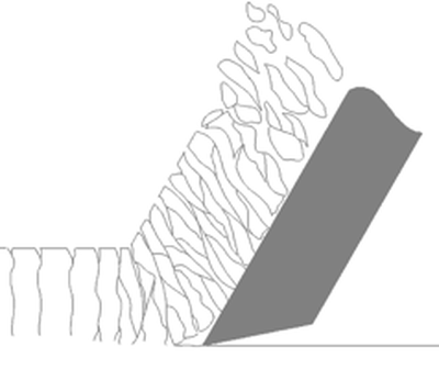
Type 2: Continuous Chip
Medium to High carbon and alloy Steels – Long Chipping Materials
“Continuous Chip - Continuous chips are a continuous ribbon produced when the flow of metal next to the tool face is not greatly restricted by a built-up edge or friction at the chip tool interface. The continuous ribbon chip is considered ideal for efficient cutting action because it results in better finishes. Unlike the Type 1 chip, fractures or ruptures do not occur here, because of the ductile nature of the metal.”
“Continuous Chip - Continuous chips are a continuous ribbon produced when the flow of metal next to the tool face is not greatly restricted by a built-up edge or friction at the chip tool interface. The continuous ribbon chip is considered ideal for efficient cutting action because it results in better finishes. Unlike the Type 1 chip, fractures or ruptures do not occur here, because of the ductile nature of the metal.”
| | Carbon and Alloy Steels such as 1030, 1035, 1045, 1144, 4130, 4140, 4340 contain at least .3% carbon that allows them to be hardened by heating and quenching. They produce long continuous chips. When machining these metals with Carbide Inserts the material in front of the cutting edge deforms resulting in high temperatures which softens the metal and consequently lowers it's strength and hardness making it easier to machine. The chips weaken and begin to break in front the cutting edge; the tool acts much in the same way that a wedge does when splitting wood. In some cases, air, oil or coolant quenches the hot chips, hardening them and making them brittle and easier to break. The chips produced when cutting these metals contact the face of the tool behind the cutting edge creating a zone of high heat that can result in cratering. Coatings usually eliminate this problem. Type 2: Continuous chip materials are the other area where many of our competitors have focused their attention. |
Type 3: Sheared Chips
Low carbon Steels, Stainless Steels, Nickel Alloys, Titanium, Copper, Aluminum and other soft, “gummy’ Materials.
Sheared Chips or as some refer to it “Continuous Chip with a Built-up Edge (BUE). The metal ahead of the cutting tool is compressed and forms a chip which begins to flow along the chip-tool interface.
Sheared Chips or as some refer to it “Continuous Chip with a Built-up Edge (BUE). The metal ahead of the cutting tool is compressed and forms a chip which begins to flow along the chip-tool interface.
 | As a result of the high temperature, the high pressure, and the high frictional resistance against the flow of the chip along the chip-tool interface, small particles of metal begin adhering to the edge of the cutting tool while the chip shears away. As the cutting process continues, more particles adhere to the cutting tool and a larger build-up results, which affects the cutting action. The built-up edge increases in size and becomes more unstable. Eventually a point is reached where fragments are torn off. Portions of these fragments break off and stick to both the chip and the workpiece. The build-up and breakdown of the built-up edge occur rapidly during a cutting action and cover the machined surface with a multitude of built-up fragments. These fragments adhere to and score the machined surface, resulting in a poor surface finish. |
These metals readily deform in front of the cutting edge and have to be "sheared" by the tool. What the above paragraph doesn’t tell you is that these materials require tools with sharper cutting edges than those used for machining cast Iron or higher carbon content Steels. The chips tend to compress onto the face of the tool which can result in built-up edge.
The chips formed when cutting these metals are thicker than those produced by Medium Carbon or Alloy Steels at the same Feed Rates and Depths of Cut. These thicker chips are stronger and harder to break. Destiny Tool, through a combination of rake face geometry, carbide substrate and concentricity tolerance is able to enable the chip to more readily "separate from itself" which not only improves MRR, but also reduced heat into the end mill and thereby extends tool life as the feed rate increases.
High strength metals such as Stainless Steel, Nickel Alloys and Titanium generate high heat and high cutting pressures in the area of the cutting edge. This results in reduced tool life compared to easier to machine materials.
- This article was originally written in 2001
- Portions of this have been edited from http://www.manufacturingcenter.com/tooling/archives/0101/0101bk.asp
- Plastic Deformation image by Jutka Czirok, Design Technology and ICT Teacher
- Special thanks to Charles Colerich, who created these drawings for me in 1994.


 RSS Feed